Supercharge Your Innovation With Domain-Expert AI Agents!

Heat exchanger and heat exchange structure of outdoor equipment internal device

A technology of heat exchangers and outdoor equipment, which is applied to the modification of electrical equipment components, electrical components, and power electronics, and can solve problems such as failure to achieve IP6X protection level, damage to heat exchange fans, and influence on inverter operation. Achieve the effect of reducing the cost of the whole machine, improving the heat exchange efficiency and improving the protection level

Pending Publication Date: 2021-02-05
TBEA XIAN ELECTRIC TECH +1
View PDF11 Cites 0 Cited by
  • Summary
  • Abstract
  • Description
  • Claims
  • Application Information

AI Technical Summary

Problems solved by technology

[0004] (1) The heat of the rest of the components inside the inverter is discharged to the outside of the inverter by means of direct blowing by the fan; although this method can meet the heat dissipation requirements of the rest of the components inside the inverter, the heat dissipation fan will also dissipate the dust Bringing it into the inverter will affect the operation of the inverter. This solution is not recommended for outdoor inverters
[0005] (2) Add a heat exchanger in the cabinet to discharge the heat generated by the rest of the components inside the cabinet to the outside of the inverter through heat exchange. This method can meet the needs of heat dissipation and dust prevention. In the inverter, the protection level of the heat exchange fan is only IP4X, which cannot reach the IP6X protection level required by the outdoor inverter, so the heat exchange fan will be damaged.

Method used


Image

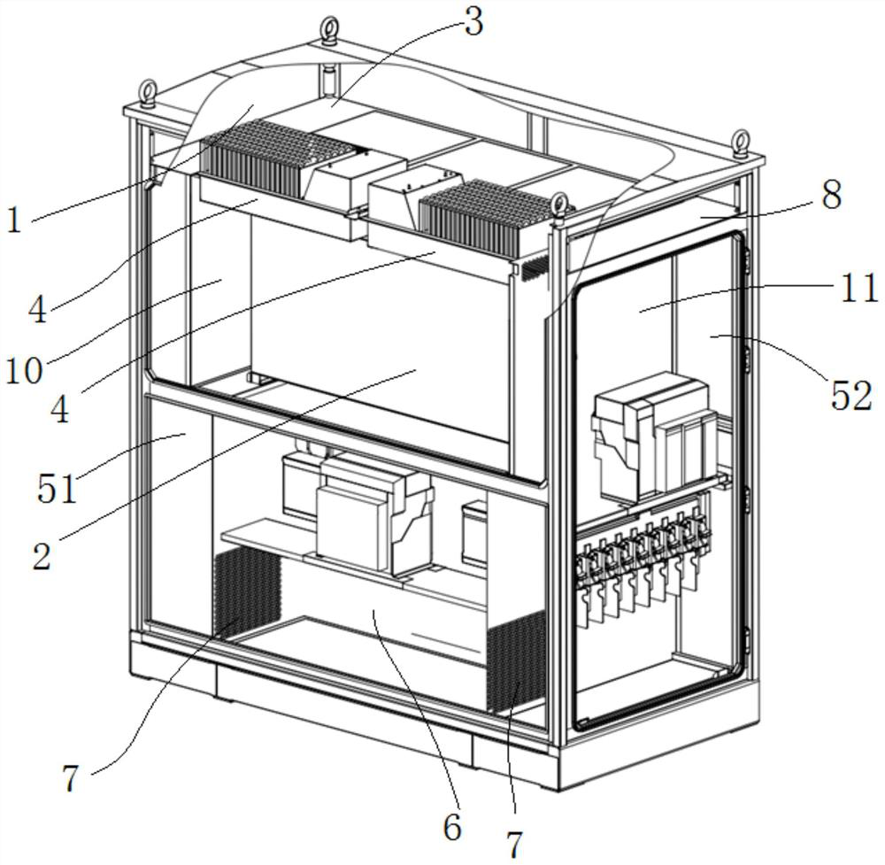
  • Heat exchanger and heat exchange structure of outdoor equipment internal device
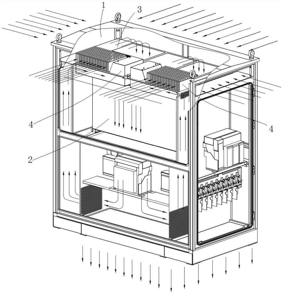
  • Heat exchanger and heat exchange structure of outdoor equipment internal device
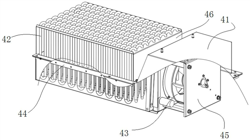
  • Heat exchanger and heat exchange structure of outdoor equipment internal device

Examples


Embodiment Construction

[0032] In order to make the purpose and technical solution of the present invention clearer and easier to understand. The present invention will be further described in detail below in conjunction with the drawings and embodiments. The specific embodiments described here are only used to explain the present invention, not to limit the present invention.

[0033] In describing the present invention, it should be understood that the terms "center", "longitudinal", "transverse", "upper", "lower", "front", "rear", "left", "right", " The orientations or positional relationships indicated by "vertical", "horizontal", "top", "bottom", "inner" and "outer" are based on the orientations or positional relationships shown in the drawings, and are only for the convenience of describing the present invention and Simplified descriptions, rather than indicating or implying that the device or element referred to must have a particular orientation, be constructed and operate in a particular ori...


PUM


Abstract

The invention discloses a heat exchanger and a heat exchange structure of an outdoor equipment internal device. The heat exchanger comprises a shell, a heat dissipation fan and a heat pipe; the lowerpart of the heat pipe is located in the shell, the heat dissipation fan is installed at one end of the heat pipe and located in the shell, and the other end of the shell is provided with a shell air inlet. According to the heat exchanger, the heat pipe is divided into the upper portion and the lower portion, the upper portion is communicated with the outside and used for heat dissipation, the lower portion transmits heat through the shell air inlet, the heat enters the lower portion of the heat pipe in the shell from the shell ventilation opening and flows out through the lower portion of theheat pipe, so as to avoid the situation that the cold air enters the heat exchanger to bring dust into the outdoor equipment to be cooled, so that other devices in the inverter are completely isolatedfrom the external environment to achieve the dustproof purpose; meanwhile, the heat dissipation requirements of the other devices in the inverter are also met.

Description

technical field [0001] The invention belongs to the technical field of outdoor inverter heat exchange, and in particular relates to a heat exchanger and a heat exchange structure of internal components of outdoor equipment. Background technique [0002] With the continuous reduction of the price of centralized inverters, the container inverter solution is gradually eliminated by the market due to its high cost price. In order to improve the profit margin of centralized inverters, various inverter manufacturers have launched outdoor dedicated photovoltaic inverters. With many advantages such as convenient installation, it has gradually occupied a dominant position in the market. Taking the current mainstream centralized 3.125MW inverter in the market as an example, various manufacturers have launched corresponding centralized outdoor photovoltaic inverters. [0003] Since the outdoor inverter is placed directly in the external environment, its internal components are more se...

Claims


Application Information

Patent Timeline
Patent Type & Authority Applications(China)
IPC IPC(8): H05K7/20
CPCH05K7/20936H05K7/20909
Inventor 胡雷雷陈伟张融森周俊杰张燕
Owner TBEA XIAN ELECTRIC TECH
Features
  • R&D
  • Intellectual Property
  • Life Sciences
  • Materials
  • Tech Scout
  • Unparalleled Data Quality
  • Higher Quality Content
  • 60% Fewer Hallucinations
Learn More