Raw material extraction and concentration all-in-one machine for cosmetic production and operation method thereof
A technology of cosmetics and all-in-one machine, which is applied in the direction of chemical instruments and methods, separation methods, evaporator accessories, etc. It can solve the problems that the raw materials cannot be fully stirred, the extraction and concentration cannot be carried out at the same time, and the purity of the extract is not high, so as to improve the extraction. Effects on efficiency and extraction quality
Pending Publication Date: 2021-02-09
李曼曼
0 Cites 0 Cited by
AI-Extracted Technical Summary
Problems solved by technology
[0003] The purpose of the present invention is to overcome the problems of low working efficiency, inability to fully stir the raw materials, low purity of the extract, and simultaneous extraction and concentration in the extraction process of existing cosmetic raw materials, and to provide a method with reasonable structural ...
Method used
Preferably, described cam 4 is set to oval structure, and is provided with spring 30 on the column 22 between adjusting plate 5 and positioning block 20, and motor-3 drives transmission shaft-23 and is installed in transmission The elliptical cam 4 on the shaft 23 rotates, and the cam 4 periodically pushes the adjustment plate 5 down. When the cam 4 presses the adjustment plate 5 downward, the adjustment plate 5 descends along the column 22 and presses the spring 30. After the adjustment plate 5 is separated, the elastic force of the spring 30 pushes the adjustment plate 5 up, realizing that the adjustment plate 5 drives the motor 2 6, the transmission shaft 2 32, and the driven shaft 7 to rise or fall, so that the material barrel 8 drives the raw material in the extraction liquid. to achieve full contact between the raw material and the extraction liquid, and to fully extract the raw material. The driven shaft 7 drives the stirring plate 38 to rise or fall between the cylinder body 1 and the material barrel 8, and the Fully agitate the extracting solution in between, so that the extracting solution with low concentration enters into the material barrel 8 through the leak hole 40 on the material barrel 8, and the high concentration extracting solution flows out from the leak hole 40 on the material barrel 8, and the material barrel 8 The raw materials inside are fully extracted to improve the extraction efficiency and quality of raw materials. The four motors 13 can drive the four cams 4 to rotate synchronously, so that the adjustment plate 5 can rise or fall at the same time, and the four cams 4 can also be rotated asynchronously. The adjusting plate 5 is raised or lowered asynchronously, so that one end is high and the other end is low, and the extract and concentrate in the barrel 1 are fully stirred to improve the treatment effect of the extract and concentrate.
Preferably, described cylinder 1 side wall is provided with interlayer 12, is provided with medium inlet pipe 16, medium outlet pipe 17 on cylinder body 1 outer wall, interlayer 12 and medium inlet pipe 16, medium outlet pipe 17 is connected, and a sealing cover 18 is movable on the discharge pipe 14 at the bottom of the cylinder 1. The heat medium is injected into the interlayer 12 through the medium inlet pipe 16, and the heat carried by the heat medium is transferred to the extraction liquid in the cylinder 1. , provide heat for the extraction of the raw material and the concentration of the extract, improve the extraction efficiency of the raw material, and also improve the concentration efficiency and concentration quality of the extract, and connect the sealing cover 18 and the discharge pipe 14 by threads to facilitate the sealing cover 18 in The installation or disassembly of the discharge pipe 14 improves the discharge efficiency of the concentrated extraction liquid from the cylinder 1 .
Preferably, described cylinder body 1 side wall is provided with interlayer 12, is provided with medium inlet pipe 16, medium outlet pipe 17 on cylinder body 1 outer wall, interlayer 12 and medium inlet pipe 16, medium outlet pipe 17 is connected, and a sealing cover 18 is movable on the discharge pipe 14 at the bottom of the cylinder 1. The heat medium is injected into the interlayer 12 through the medium inlet pipe 16, and the heat carried by the heat medium is transferred to the extraction liquid in the cylinder 1. , provide heat for the extraction of the raw material and the concentration of the extract, improve the extraction efficiency of the raw material, and also improve the concentration efficiency and concentration quality of the extract, and connect the sealing cover 18 and the discharge pipe 14 by threads to facilitate the sealing cover 18 in The installation or disassembly of the discharge pipe 14 improves the discharge efficiency of the concentrated extraction liquid from the cylinder 1 .
Preferably, described driven shaft 7 is set to hollow structure, is provided with connecting pipe 42 at the top of driven shaft 7, connects with steam pipe 41 after connecting pipe 42 top passes through cover body 2, and A sealing ring 43 is arranged between the driven shaft 7 and the connecting pipe 42, and the steam with heat is transported from the steam pipe 41 and the connecting pipe 42 to the hollow driven shaft 7 by the steam pump 9, and the steam from the driven shaft 7 The bottom end is discharged into the extraction liquid between the inner wall of the cylinder body 1 and the material barrel 8, and the temperature of the extraction liquid is raised to facilitate the full extraction of raw materials. On the other hand, during the process of concentrating the extraction liquid, the steam with heat It can provide heat for the extraction liquid in the concentration process, improve the extraction and concentration efficiency of raw materials and the quality of extraction and concentration, and improve the sealing performance between the driven shaft 7 and the connecting pipe 42 through the sealing ring 43, so as to prevent steam with heat from The flow between the moving shaft 7 and the connecting pipe 42 allows the steam to fully flow into the extraction liquid, which improves the utilization efficiency of the steam. A hole for the connecting pipe 42 to move up and down is provided on the top of the cover body 2, which is convenient for the adjustment plate 5 to drive. The driven shaft 7 and the connecting pipe 42 connected with the driven shaft 7 rise or fall to improve the stability of the extraction and concentration integrated machine during work.
Preferably, described transmission shaft 2 32 vertically passes through material barrel 8, screens, and limit ring 44 is set at the bottom of material barrel 8, and stop ring 46 is provided on sieve plate 13, and transmission shaft 2 32 The bottom end is provided with a stirring rod 48 through the mounting ring 47, a push plate 45 is arranged on the transmission shaft 2 32 between the sieve plate 13 and the material bucket 8, and a sealing layer 49 is arranged on the side wall of the sieve plate 13, and the The push plate 45 is install...
Abstract
The invention discloses a raw material extraction and concentration all-in-one machine for cosmetic production, which comprises a cylinder body, a cover body, a motor I, a cam, an adjusting plate, a motor II, a driven shaft, a material barrel and a steam pump, and is characterized in that a connecting rod and a steam exhaust pipe are arranged on the front surface of the adjusting plate, the motorII is arranged on a bearing plate, and the driven shaft vertically penetrates through a bearing II; a driven wheel is arranged at the top end of the driven shaft, a stirring plate is arranged on the driven shaft under the adjusting plate, and the top of the material barrel is movably connected with a fixing ring. Raw materials needing to be extracted and concentrated are put into the material barrel, an extracting solution conveniently enters the material barrel and carries nutrient substances to flow out of the material barrel through the leakage holes, the material barrel is taken down fromthe fixing ring after raw material extraction and concentration are completed, extracted raw material residues are conveniently treated, the raw materials can be conveniently separated from the extracting solution and the concentrated solution through the material barrel, and the purity of the extracting solution and the concentrated solution is improved.
Application Domain
Evaporator accessoriesGrain treatments
Technology Topic
Electric machineryProcess engineering +7
Image
Examples
- Experimental program(2)
Example Embodiment
[0033] Example 1
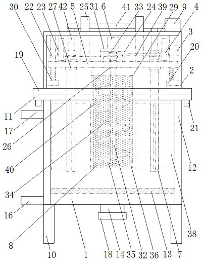
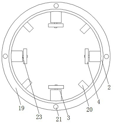
[0034] as attached Figure 1-7 As shown, an all-in-one machine for extracting and concentrating raw materials for cosmetic production includes a cylinder body 1, a cover body 2, a motor one 3, a cam 4, a regulating plate 5, a motor two 6, a driven shaft 7, a material barrel 8 and a steam pump 9 , the cylinder body 1 is arranged on the bracket 10, and a discharge pipe 14 is arranged at the bottom of the cylinder body 1, and the cylinder body 1 and the bracket 10 are connected by welding, which improves the connection between the cylinder body 1 and the bracket 10. Strength, enhance the structural strength of the cylinder body 1, the cover body 2 is movably connected with the cylinder body 1, a positioning block 20 is arranged on the inner wall of the cover body 2, and a column is arranged between the top of the cover body 2 and the positioning block 20 22. The motor one 3 is arranged on the inner wall of the cover body 2, and the motor one 3 is provided with a transmission shaft one 23, the cam 4 is installed on the transmission shaft one 23, and the motor one 3 drives the transmission shaft one 23. And the cam 4 installed on the transmission shaft 1 23 rotates, the cam 4 periodically pushes the adjustment plate 5 down, and when the cam 4 presses the adjustment plate 5 downward, the adjustment plate 5 descends along the column 22 and compresses the spring 30. 4 After being separated from the adjustment plate 5, the elastic force of the spring 30 pushes the adjustment plate 5 upward, so that the adjustment plate 5 drives the motor 2 6, the transmission shaft 2 32, and the driven shaft 7 to rise or fall, so that the material barrel 8 drives the raw material to move up or down. The extraction liquid rises or falls to achieve full contact between the raw material and the extraction liquid, and the raw material is fully extracted. The driven shaft 7 drives the stirring plate 38 to rise or fall between the cylinder body 1 and the material barrel 8. The extraction liquid between 8 and 8 is fully stirred, so that the extraction liquid with low concentration enters into the material barrel 8 through the leak hole 40 on the material barrel 8, and the extraction liquid with high concentration flows out from the leak hole 40 on the material barrel 8. The raw materials in the barrel 8 are fully extracted to improve the extraction efficiency and extraction quality of the raw materials. The steam pump 9 is arranged on the cover body 2, and a steam transmission pipe 41 is arranged on the steam pump 9. The hot steam is transported from the steam pipe 41 and the connecting pipe 42 to the hollow driven shaft 7, and is discharged from the bottom end of the driven shaft 7 into the extraction liquid between the inner wall of the cylinder 1 and the material barrel 8, and the extraction On the other hand, in the process of concentrating the extract, the steam with heat can provide heat for the extract in the concentration process, and improve the extraction and concentration efficiency of the raw materials and the quality of extraction and concentration. , the sealing between the driven shaft 7 and the connecting pipe 42 is improved by the sealing ring 43, and the hot steam is prevented from flowing out between the driven shaft 7 and the connecting pipe 42, so that the steam can fully flow into the extraction liquid, and the steam is improved. It is characterized in that: a connecting rod 24 and a steam exhaust pipe 25 are arranged on the front of the regulating plate 5, a bearing plate 31 is arranged on the connecting rod 24, a bearing 26 is arranged on the regulating plate 5, and a bearing plate 26 is arranged on the regulating plate 5. The adjusting plate 5 on both sides of the bearing one 26 is provided with a bearing two 27, a connecting hole 28 is provided on the edge of the adjusting plate 5, a fixing ring 29 is provided on the back of the adjusting plate 5, and the column 22 is vertically passed through the connecting hole. 28. The second motor 6 is arranged on the bearing plate 31, and the second motor 6 is provided with a second transmission shaft 32, and the second transmission shaft 32 is vertically passed through the first bearing. 26. A driving wheel 33 is provided on the second transmission shaft 32 between the bearing plate 31 and the adjustment plate 5, a feeding plate 34 is arranged on the second transmission shaft 32 under the adjustment plate 5, and a bottom end of the transmission shaft 2 32 is arranged There is a connecting ring 35, and a crushing rod 36 is arranged on the connecting ring 35. The driven shaft 7 vertically passes through the bearing two 27, and a driven wheel 37 is arranged at the top of the driven shaft 7, and is below the adjusting plate 5. The second driven shaft 7 is provided with a stirring plate, the second motor 6 drives the second transmission shaft 32 to rotate, the second transmission shaft 32 drives the driven shaft 7 to rotate through the belt 39, and the second transmission shaft 32 drives the lifting plate 34 and the crushing rod 36 to rotate, Stir and pulverize the raw materials in the material barrel 8 to fully extract the raw materials, and the driven shaft 7 drives the stirring plate 38 to rotate, so that the extraction liquid with low concentration enters the material barrel 8 through the leak hole 40 on the material barrel 8, and the concentration is high. The extracted liquid flows out from the leak hole 40 on the material barrel 8, fully extracts the raw materials in the material barrel 8, and improves the extraction efficiency and extraction quality of the raw materials. The side wall and bottom of the material barrel 8 are provided with leakage holes 40. The material barrel 8 and the fixing ring 29 are connected by threads, and the raw materials that need to be extracted and concentrated are put into the material barrel 8, and the leakage holes 40 are convenient for the extraction liquid to enter the material. The inside of the barrel 8 and the carrying nutrients flow out from the material barrel 8. After the extraction and concentration of the raw materials are completed, the material barrel 8 is removed from the fixing ring 29, so as to facilitate the processing of the extracted raw material slag. The raw material is separated from the extract and the concentrate, which improves the purity of the extract and the concentrate.
[0035] Preferably, the top outer edge of the cylinder body 1 is provided with a positioning plate 11, the positioning plate one 11 is provided with a positioning hole 15, and the inner bottom of the cylinder body 1 is provided with a transverse structure sieve plate 13, the cover body 2. The outer edge of the bottom is provided with a positioning plate 2 19, and a positioning column 21 is arranged on the positioning plate 2 19, and the positioning column 21 is vertically extended into the positioning hole 15. 15. The positioning column 21 can improve the connection stability between the cylinder body 1 and the cover body 2, and can also improve the sealing performance between the cylinder body 1 and the cover body 2. Impurities are discharged from the discharge pipe 14 with the concentrated raw material extract, which improves the purity of the concentrated extract.
[0036] Preferably, an interlayer 12 is provided on the side wall of the cylinder body 1, and a medium inlet pipe 16 and a medium outlet pipe 17 are arranged on the outer wall of the cylinder body 1, so that the interlayer 12 is communicated with the medium inlet pipe 16 and the medium outlet pipe 17, A sealing cover 18 is movably arranged on the discharge pipe 14 at the bottom of the cylinder body 1, and the heat medium is injected into the interlayer 12 through the medium inlet pipe 16, and the heat carried by the heat medium is transferred to the extraction liquid in the cylinder body 1, which is the raw material. The extraction and the concentration of the extraction liquid provide heat, improve the extraction efficiency of the raw materials, and also improve the concentration efficiency and concentration quality of the extraction liquid. The installation or disassembly on the 14 improves the discharge efficiency of the concentrated extract from the cylinder 1 .
[0037] Preferably, the cam 4 is arranged in an elliptical structure, and a spring 30 is sleeved on the upright column 22 between the adjustment plate 5 and the positioning block 20 , and the motor 1 3 drives the transmission shaft 1 23 and is installed on the transmission shaft 1 23 The upper oval cam 4 rotates, and the cam 4 periodically pushes the adjustment plate 5 to descend. When the cam 4 presses the adjustment plate 5 downward, the adjustment plate 5 descends along the column 22 and presses the spring 30. After separation, the elastic force of the spring 30 pushes the adjustment plate 5 upward, so that the adjustment plate 5 drives the second motor 6, the second transmission shaft 32, and the driven shaft 7 to rise or fall, so that the material bucket 8 drives the raw material to rise or fall in the extraction liquid. Descending to achieve full contact between the raw material and the extraction liquid, fully extracting the raw material, the driven shaft 7 drives the stirring plate 38 to rise or fall between the cylinder 1 and the material barrel 8, and the extraction between the cylinder 1 and the material barrel 8 The liquid is fully stirred, so that the extraction liquid with low concentration enters into the material barrel 8 through the leakage hole 40 on the material barrel 8, and the extraction liquid with high concentration flows out from the leakage hole 40 on the material barrel 8, and the raw material in the material barrel 8 Carry out sufficient extraction to improve the extraction efficiency and extraction quality of raw materials. The four motors 1 3 can drive the four cams 4 to rotate synchronously, so that the adjustment plate 5 can rise or fall at the same time, or the four cams 4 can be rotated asynchronously, so that the adjustment plate 5. It rises or falls asynchronously, showing a state of one end being high and one end being low. The extraction liquid and concentrated liquid in the cylinder 1 are fully stirred to improve the treatment effect of the extraction liquid and concentrated liquid.
[0038] Preferably, the steam exhaust pipe 25 on the regulating plate 5 penetrates from the top of the cover body 2. During the extraction liquid concentration process, the water vapor in the extraction liquid is discharged from the steam exhaust pipe 25, and the extraction liquid is rapidly concentrated. In order to improve the concentration efficiency and concentration quality of the extract, the top of the cover body 2 is provided with a hole for the steam supply and exhaust pipe 25 to move up and down, so that the adjustment plate 5 can drive the exhaust pipe 25 to rise or fall, so as to improve the extraction and concentration efficiency of raw materials.
[0039] Preferably, the driving wheel 33 on the second transmission shaft 32 is connected with the driven wheel 37 on the driven shaft 7 through the belt 39 , the second motor 6 drives the second transmission shaft 32 to rotate, and the second transmission shaft 32 drives the driven shaft through the belt 39 . The shaft 7 rotates, the second transmission shaft 32 drives the feeding plate 34 and the pulverizing rod 36 to rotate, agitates and pulverizes the raw materials in the material barrel 8, and fully extracts the raw materials, and the driven shaft 7 drives the stirring plate 38 to rotate, so that the extraction of low concentration The liquid enters the material barrel 8 through the leakage hole 40 on the material barrel 8, and the extraction liquid with high concentration flows out from the leakage hole 40 on the material barrel 8, and fully extracts the raw materials in the material barrel 8 to improve the extraction efficiency of raw materials and Extraction quality.
[0040]Preferably, the driven shaft 7 is set to a hollow structure, and a connecting pipe 42 is provided at the top of the driven shaft 7. After the top of the connecting pipe 42 is passed through the cover body 2, it is connected to the steam pipe 41, and is connected to the steam pipe 41 after the driven shaft 7 is driven. A sealing ring 43 is arranged between the shaft 7 and the connecting pipe 42, and the steam with heat is transported from the steam pipe 41 and the connecting pipe 42 to the hollow driven shaft 7 through the steam pump 9, and from the bottom end of the driven shaft 7. It is discharged into the extraction liquid between the inner wall of the cylinder 1 and the material barrel 8, and the temperature of the extraction liquid is heated to facilitate the full extraction of the raw materials. On the other hand, during the concentration process of the extraction liquid, the steam with heat can be concentrated. The extraction liquid in the process provides heat, improves the extraction and concentration efficiency and quality of extraction and concentration of raw materials, improves the sealing between the driven shaft 7 and the connecting pipe 42 through the sealing ring 43, and avoids the steam driven shaft 7 with heat. It flows out from the connection pipe 42, so that the steam can fully flow into the extraction liquid, and the utilization efficiency of the steam is improved. The top of the cover body 2 is provided with a hole for the connection pipe 42 to move up and down, which is convenient for the adjustment plate 5 to drive the driven shaft. 7 and the connecting pipe 42 connected with the driven shaft 7 rise or fall to improve the stability of the extraction and concentration integrated machine during the working process.
[0041] Preferably, the material bucket 8 is set to a structure that can be removed from the fixing ring 29, the material bucket 8 and the fixing ring 29 are connected by threads, and the raw materials that need to be extracted and concentrated are put into the material bucket 8, Through the leak hole 40, it is convenient for the extraction liquid to enter the material barrel 8 and carry nutrients to flow out from the material barrel 8. After the extraction and concentration of the raw materials are completed, the material barrel 8 is removed from the fixing ring 29, which is convenient for the extraction of the raw material residue. For processing, it is convenient to separate the raw material from the extraction liquid and the concentrated liquid through the material barrel 8, and the purity of the extraction liquid and the concentrated liquid is improved.
[0042] Preferably, the lifting plate 34 on the second transmission shaft 32 is set in a spiral structure, the second motor 6 drives the second transmission shaft 32 to rotate, the second transmission shaft 32 drives the driven shaft 7 to rotate through the belt 39, and the second transmission shaft 32 Drive the feeding plate 34 and the pulverizing rod 36 to rotate, and the pulverizing rod 36 at the bottom of the second transmission shaft 32 can pulverize the raw materials at the bottom of the material barrel 8, so that the nutrients in the raw materials can flow into the extraction liquid, and the rotating feeding plate 34 The raw material in the middle of the material barrel 8 is driven to rise, and the raw material near the inner wall of the material barrel 8 falls, so that the lifting plate 34 flips the raw material up and down in the material barrel 8, so that the raw material and the liquid are fully contacted, and the raw material is fully extracted and processed to improve the raw material. Extraction efficiency and extraction quality.
[0043] An operation method suitable for an integrated machine for extracting and concentrating raw materials for cosmetic production, characterized in that the operation method comprises the following steps:
[0044] First: Check whether the circuit of the raw material extraction and concentration integrated machine for cosmetic production is normal, and whether the motor one 3, the motor two 6, and the steam pump 9 can work normally;
[0045] Second: connect the sealing cover 18 to the discharge pipe 14, add water into the cylinder 1, inject the heat medium into the interlayer 12 through the medium inlet pipe 16, add the cosmetic raw materials into the material barrel 8, and put the top of the material barrel 8 Installed in the fixing ring 29, and the cover body 2 is installed on the cylinder body 1;
[0046] Third: start the motor 1 3, the motor 1 3 drives the transmission shaft 1 23 and the cam 4 installed on the transmission shaft 1 23 to rotate, the cam 4 periodically pushes the adjustment plate 5 down, starts the motor 2 6, and the motor 2 6 drives the transmission The second shaft 32 rotates, the driving wheel 33 on the second transmission shaft 32 drives the driven wheel 37 on the driven shaft 7 to rotate through the belt 39, and drives the driven shaft 7 and the stirring plate on the driven shaft 7 to rotate, and the second transmission shaft 32 drives the rotation. The feeding plate 34 and the pulverizing rod 36 rotate to lift and pulverize whatever is in the material barrel 8 and stir whatever is in the material barrel 8. The stirring plate 38 on the driven shaft 7 agitates the space between the barrel 1 and the material barrel 8. liquid, extract the material in the material barrel 8;
[0047] Fourth: During the material extraction process, the heat medium is continuously injected into the interlayer 12 through the medium inlet pipe 16. After the material extraction is completed, the steam pump 9 is started, and the steam pump 9 sends the steam through the steam transmission pipe 41, the connecting pipe 42, and the hollow space. The driven shaft 7 enters into the liquid between the cylinder 1 and the material barrel 8 to provide heat for the concentration of the material extraction liquid;
[0048] Fifth: after the material extraction and concentration are completed, open the sealing cover 18 in row 14 of the discharge pipe, discharge the concentrated extract from the discharge pipe, and collect the discharged concentrate;
[0049] Sixth: After the material extraction, concentration and processing are completed, turn off the steam pump 9, motor one 3, motor two 6, remove the cover body 2 from the cylinder body 1, and remove the material barrel 8 from the fixing ring 29, Clean up impurities generated in the process of extraction and concentration of materials, and cut off the power supply.
Example Embodiment
[0050] Embodiment 2
[0051] as attached Figure 8-9 As shown, an all-in-one machine for extracting and concentrating raw materials for cosmetic production includes a cylinder body 1, a cover body 2, a motor one 3, a cam 4, a regulating plate 5, a motor two 6, a driven shaft 7, a material barrel 8 and a steam pump 9 , the cylinder body 1 is arranged on the bracket 10, and a discharge pipe 14 is arranged at the bottom of the cylinder body 1, and the cylinder body 1 and the bracket 10 are connected by welding, which improves the connection between the cylinder body 1 and the bracket 10. Strength, enhance the structural strength of the cylinder body 1, the cover body 2 is movably connected with the cylinder body 1, a positioning block 20 is arranged on the inner wall of the cover body 2, and a column is arranged between the top of the cover body 2 and the positioning block 20 22. The motor one 3 is arranged on the inner wall of the cover body 2, and the motor one 3 is provided with a transmission shaft one 23, the cam 4 is installed on the transmission shaft one 23, and the motor one 3 drives the transmission shaft one 23. And the cam 4 installed on the transmission shaft 1 23 rotates, the cam 4 periodically pushes the adjustment plate 5 down, and when the cam 4 presses the adjustment plate 5 downward, the adjustment plate 5 descends along the column 22 and compresses the spring 30. 4 After being separated from the adjustment plate 5, the elastic force of the spring 30 pushes the adjustment plate 5 upward, so that the adjustment plate 5 drives the motor 2 6, the transmission shaft 2 32, and the driven shaft 7 to rise or fall, so that the material barrel 8 drives the raw material to move up or down. The extraction liquid rises or falls to achieve full contact between the raw material and the extraction liquid, and the raw material is fully extracted. The driven shaft 7 drives the stirring plate 38 to rise or fall between the cylinder body 1 and the material barrel 8. The extraction liquid between 8 and 8 is fully stirred, so that the extraction liquid with low concentration enters into the material barrel 8 through the leak hole 40 on the material barrel 8, and the extraction liquid with high concentration flows out from the leak hole 40 on the material barrel 8. The raw materials in the barrel 8 are fully extracted to improve the extraction efficiency and extraction quality of the raw materials. The steam pump 9 is arranged on the cover body 2, and a steam transmission pipe 41 is arranged on the steam pump 9. The hot steam is transported from the steam pipe 41 and the connecting pipe 42 to the hollow driven shaft 7, and is discharged from the bottom end of the driven shaft 7 into the extraction liquid between the inner wall of the cylinder 1 and the material barrel 8, and the extraction On the other hand, in the process of concentrating the extract, the steam with heat can provide heat for the extract in the concentration process, and improve the extraction and concentration efficiency of the raw materials and the quality of extraction and concentration. , the sealing between the driven shaft 7 and the connecting pipe 42 is improved by the sealing ring 43, and the hot steam is prevented from flowing out between the driven shaft 7 and the connecting pipe 42, so that the steam can fully flow into the extraction liquid, and the steam is improved. It is characterized in that: a connecting rod 24 and a steam exhaust pipe 25 are arranged on the front of the regulating plate 5, a bearing plate 31 is arranged on the connecting rod 24, a bearing 26 is arranged on the regulating plate 5, and a bearing plate 26 is arranged on the regulating plate 5. The adjusting plate 5 on both sides of the bearing one 26 is provided with a bearing two 27, a connecting hole 28 is provided on the edge of the adjusting plate 5, a fixing ring 29 is provided on the back of the adjusting plate 5, and the column 22 is vertically passed through the connecting hole. 28. The second motor 6 is arranged on the bearing plate 31, and the second motor 6 is provided with a second transmission shaft 32, and the second transmission shaft 32 is vertically passed through the first bearing. 26. A driving wheel 33 is provided on the second transmission shaft 32 between the bearing plate 31 and the adjustment plate 5, a feeding plate 34 is arranged on the second transmission shaft 32 under the adjustment plate 5, and a feeding plate 34 is arranged on the second transmission shaft 32. The connecting ring 35 is provided with a crushing rod 36, the driven shaft 7 vertically passes through the second bearing 27, a driven wheel 37 is arranged at the top of the driven shaft 7, The driven shaft 7 is provided with a stirring plate, the second motor 6 drives the second transmission shaft 32 to rotate, the second transmission shaft 32 drives the driven shaft 7 to rotate through the belt 39, and the second transmission shaft 32 drives the feeding plate 34 and the crushing rod 36 to rotate, stirring , crush the raw materials in the material barrel 8, fully extract the raw materials, and the driven shaft 7 drives the stirring plate 38 to rotate, so that the extraction liquid with low concentration enters the material barrel 8 through the leak hole 40 on the material barrel 8, and the high concentration The extraction liquid flows out from the leak hole 40 on the material barrel 8, fully extracts the raw materials in the material barrel 8, and improves the extraction efficiency and extraction quality of the raw materials. The side wall and bottom of the barrel 8 are provided with leakage holes 40. The material barrel 8 and the fixing ring 29 are connected by threads, and the raw materials that need to be extracted and concentrated are put into the material barrel 8, and the leakage hole 40 is convenient for the extraction liquid to enter the material barrel. 8 and carrying nutrients flow out from the material barrel 8. After the extraction and concentration of the raw materials are completed, the material barrel 8 is removed from the fixing ring 29, so as to facilitate the processing of the extracted raw material slag, and it is convenient to pass the material barrel 8 to the raw material. It is separated from the extract and the concentrate to improve the purity of the extract and the concentrate.
[0052] Preferably, a positioning plate 11 is provided on the outer edge of the top of the cylindrical body 1, a positioning hole 15 is provided on the positioning plate 1 11, and a sieve plate 13 with a transverse structure is movably provided at the inner bottom of the cylindrical body 1. The cover A positioning plate 2 19 is arranged on the outer edge of the bottom of the body 2, a positioning column 21 is arranged on the second positioning plate 19, and the positioning column 21 is vertically extended into the positioning hole 15. The hole 15 and the positioning post 21 can improve the connection stability between the cylinder body 1 and the cover body 2, and can also improve the sealing performance between the cylinder body 1 and the cover body 2. The extraction liquid of the raw material can be filtered through the filter screen, It is avoided that impurities are discharged from the discharge pipe 14 with the concentrated raw material extraction liquid, and the purity of the concentrated extraction liquid is improved.
[0053] Preferably, an interlayer 12 is provided on the side wall of the cylinder body 1, and a medium inlet pipe 16 and a medium outlet pipe 17 are arranged on the outer wall of the cylinder body 1, so that the interlayer 12 is communicated with the medium inlet pipe 16 and the medium outlet pipe 17, A sealing cover 18 is movably arranged on the discharge pipe 14 at the bottom of the cylinder body 1, and the heat medium is injected into the interlayer 12 through the medium inlet pipe 16, and the heat carried by the heat medium is transferred to the extraction liquid in the cylinder body 1, which is the raw material. The extraction and the concentration of the extraction liquid provide heat, improve the extraction efficiency of the raw materials, and also improve the concentration efficiency and concentration quality of the extraction liquid. The installation or disassembly on the 14 improves the discharge efficiency of the concentrated extract from the cylinder 1 .
[0054] Preferably, the cam 4 is arranged in an elliptical structure, and a spring 30 is sleeved on the upright column 22 between the adjustment plate 5 and the positioning block 20 , and the motor 1 3 drives the transmission shaft 1 23 and is installed on the transmission shaft 1 23 The upper oval cam 4 rotates, and the cam 4 periodically pushes the adjustment plate 5 to descend. When the cam 4 presses the adjustment plate 5 downward, the adjustment plate 5 descends along the column 22 and presses the spring 30. After separation, the elastic force of the spring 30 pushes the adjustment plate 5 upward, so that the adjustment plate 5 drives the second motor 6, the second transmission shaft 32, and the driven shaft 7 to rise or fall, so that the material bucket 8 drives the raw material to rise or fall in the extraction liquid. Descending to achieve full contact between the raw material and the extraction liquid, fully extracting the raw material, the driven shaft 7 drives the stirring plate 38 to rise or fall between the cylinder 1 and the material barrel 8, and the extraction between the cylinder 1 and the material barrel 8 The liquid is fully stirred, so that the extraction liquid with low concentration enters into the material barrel 8 through the leakage hole 40 on the material barrel 8, and the extraction liquid with high concentration flows out from the leakage hole 40 on the material barrel 8, and the raw material in the material barrel 8 Carry out sufficient extraction to improve the extraction efficiency and extraction quality of raw materials. The four motors 1 3 can drive the four cams 4 to rotate synchronously, so that the adjustment plate 5 can rise or fall at the same time, or the four cams 4 can be rotated asynchronously, so that the adjustment plate 5. It rises or falls asynchronously, showing a state of one end being high and one end being low. The extraction liquid and concentrated liquid in the cylinder 1 are fully stirred to improve the treatment effect of the extraction liquid and concentrated liquid.
[0055] Preferably, the steam exhaust pipe 25 on the regulating plate 5 penetrates from the top of the cover body 2. During the extraction liquid concentration process, the water vapor in the extraction liquid is discharged from the steam exhaust pipe 25, and the extraction liquid is rapidly concentrated. In order to improve the concentration efficiency and concentration quality of the extract, the top of the cover body 2 is provided with a hole for the steam supply and exhaust pipe 25 to move up and down, so that the adjustment plate 5 can drive the exhaust pipe 25 to rise or fall, so as to improve the extraction and concentration efficiency of raw materials.
[0056] Preferably, the driving wheel 33 on the second transmission shaft 32 is connected with the driven wheel 37 on the driven shaft 7 through the belt 39 , the second motor 6 drives the second transmission shaft 32 to rotate, and the second transmission shaft 32 drives the driven shaft through the belt 39 . The shaft 7 rotates, the second transmission shaft 32 drives the feeding plate 34 and the pulverizing rod 36 to rotate, agitates and pulverizes the raw materials in the material barrel 8, and fully extracts the raw materials, and the driven shaft 7 drives the stirring plate 38 to rotate, so that the extraction of low concentration The liquid enters the material barrel 8 through the leakage hole 40 on the material barrel 8, and the extraction liquid with high concentration flows out from the leakage hole 40 on the material barrel 8, and fully extracts the raw materials in the material barrel 8 to improve the extraction efficiency of raw materials and Extraction quality.
[0057] Preferably, the driven shaft 7 is set to a hollow structure, and a connecting pipe 42 is provided at the top of the driven shaft 7. After the top of the connecting pipe 42 is passed through the cover body 2, it is connected to the steam pipe 41, and is connected to the steam pipe 41 after the driven shaft 7 is driven. A sealing ring 43 is arranged between the shaft 7 and the connecting pipe 42, and the steam with heat is transported from the steam pipe 41 and the connecting pipe 42 to the hollow driven shaft 7 through the steam pump 9, and from the bottom end of the driven shaft 7. It is discharged into the extraction liquid between the inner wall of the cylinder 1 and the material barrel 8, and the temperature of the extraction liquid is heated to facilitate the full extraction of the raw materials. On the other hand, during the concentration process of the extraction liquid, the steam with heat can be concentrated. The extraction liquid in the process provides heat, improves the extraction and concentration efficiency and quality of extraction and concentration of raw materials, improves the sealing between the driven shaft 7 and the connecting pipe 42 through the sealing ring 43, and avoids the steam driven shaft 7 with heat. It flows out from the connection pipe 42, so that the steam can fully flow into the extraction liquid, and the utilization efficiency of the steam is improved. The top of the cover body 2 is provided with a hole for the connection pipe 42 to move up and down, which is convenient for the adjustment plate 5 to drive the driven shaft. 7 and the connecting pipe 42 connected with the driven shaft 7 rise or fall to improve the stability of the extraction and concentration integrated machine during the working process.
[0058] Preferably, the material bucket 8 is set to a structure that can be removed from the fixing ring 29, the material bucket 8 and the fixing ring 29 are connected by threads, and the raw materials that need to be extracted and concentrated are put into the material bucket 8, Through the leak hole 40, it is convenient for the extraction liquid to enter the material barrel 8 and carry nutrients to flow out from the material barrel 8. After the extraction and concentration of the raw materials are completed, the material barrel 8 is removed from the fixing ring 29, which is convenient for the extraction of the raw material residue. For processing, it is convenient to separate the raw material from the extraction liquid and the concentrated liquid through the material barrel 8, and the purity of the extraction liquid and the concentrated liquid is improved.
[0059] Preferably, the lifting plate 34 on the second transmission shaft 32 is set in a spiral structure, the second motor 6 drives the second transmission shaft 32 to rotate, the second transmission shaft 32 drives the driven shaft 7 to rotate through the belt 39, and the second transmission shaft 32 Drive the feeding plate 34 and the pulverizing rod 36 to rotate, and the pulverizing rod 36 at the bottom of the second transmission shaft 32 can pulverize the raw materials at the bottom of the material barrel 8, so that the nutrients in the raw materials can flow into the extraction liquid, and the rotating feeding plate 34 The raw material in the middle of the material barrel 8 is driven to rise, and the raw material near the inner wall of the material barrel 8 falls, so that the lifting plate 34 flips the raw material up and down in the material barrel 8, so that the raw material and the liquid are fully contacted, and the raw material is fully extracted and processed to improve the raw material. Extraction efficiency and extraction quality.
[0060] Preferably, the second transmission shaft 32 vertically passes through the material barrel 8 and is screened, a limiting ring 44 is arranged at the bottom of the material barrel 8, a blocking ring 46 is arranged on the sieve plate 13, and passes through the bottom end of the second transmission shaft 32. The installation ring 47 is provided with a stirring rod 48, a push plate 45 is provided on the transmission shaft 2 32 between the sieve plate 13 and the material barrel 8, and a sealing layer 49 is provided on the side wall of the sieve plate 13, and the push plate 45 It is installed on the second transmission shaft 32 through threads, the sieve plate 13 is sleeved on the second transmission shaft 32 through the retaining ring 46, and the mounting ring 47 that drives the stirring rod 48 is installed at the bottom end of the second transmission shaft 32 through threads, and the cover body 2 is closed. During the process of the cylinder body 1, the second transmission shaft 32 pushes the sieve plate 13 into the cylinder body 1, and the push plate 45 on the second transmission shaft 32 pushes the sieve plate 13 to descend in the cylinder body 1. During the extraction and concentration of raw materials, the motor The second 6 drives the transmission shaft 2 32 to rotate, the transmission shaft 2 32 in the material barrel 8 drives the material lifting plate 34 and the crushing rod 36 to rotate, flips and crushes the raw materials in the material barrel 8, and the transmission shaft 2 32 is limited on the material barrel 8 The ring 44 and the retaining ring 46 rotate inwards, drive the installation ring 47 and the stirring rod 48 at the bottom end of the second transmission shaft 32 to rotate, and stir the extraction liquid or concentrated liquid under the sieve plate 13 to avoid the extraction liquid or concentrated liquid under the sieve plate 13. The sieve plate 13 is provided with a sealing layer 49 at the edge of the sieve plate 13 to increase the tightness between the sieve plate 13 and the cylinder 1, so as to avoid the extraction liquid above the sieve plate 13, The concentrated liquid flows under the sieve plate 13 from the edge of the sieve plate 13 and the inner wall of the cylinder 1, which can fully filter the extraction liquid and the concentrated liquid above the sieve plate 13. The mechanical seal is used for the retaining ring 46, which not only facilitates the transmission shaft The second 32 rotates and moves up and down in the baffle ring 46, which can also improve the sealing performance between the baffle ring 46 and the second transmission shaft 32, and prevent the extraction liquid and concentrated liquid above the sieve plate 13 from flowing from the baffle ring 46 and the second transmission shaft 32 to the Below the sieve plate 13, the extraction liquid and the concentrated liquid are fully screened to improve the purity of the extracted liquid and the concentrated liquid.
[0061] An operation method suitable for an integrated machine for extracting and concentrating raw materials for cosmetic production, characterized in that the operation method comprises the following steps:
[0062] First: Check whether the circuit of the raw material extraction and concentration integrated machine for cosmetic production is normal, and whether the motor one 3, the motor two 6, and the steam pump 9 can work normally;
[0063] Second: connect the sealing cover 18 to the discharge pipe 14, add water into the cylinder 1, inject the heat medium into the interlayer 12 through the medium inlet pipe 16, add the cosmetic raw materials into the material barrel 8, and put the top of the material barrel 8 Installed in the fixing ring 29, and the cover body 2 is installed on the cylinder body 1;
[0064] Third: start the motor 1 3, the motor 1 3 drives the transmission shaft 1 23 and the cam 4 installed on the transmission shaft 1 23 to rotate, the cam 4 periodically pushes the adjustment plate 5 down, starts the motor 2 6, and the motor 2 6 drives the transmission The second shaft 32 rotates, the driving wheel 33 on the second transmission shaft 32 drives the driven wheel 37 on the driven shaft 7 to rotate through the belt 39, and drives the driven shaft 7 and the stirring plate on the driven shaft 7 to rotate, and the second transmission shaft 32 drives the rotation. The feeding plate 34 and the pulverizing rod 36 rotate to lift and pulverize whatever is in the material barrel 8 and stir whatever is in the material barrel 8. The stirring plate 38 on the driven shaft 7 agitates the space between the barrel 1 and the material barrel 8. liquid, extract the material in the material barrel 8;
[0065] Fourth: During the material extraction process, the heat medium is continuously injected into the interlayer 12 through the medium inlet pipe 16. After the material extraction is completed, the steam pump 9 is started, and the steam pump 9 sends the steam through the steam transmission pipe 41, the connecting pipe 42, and the hollow space. The driven shaft 7 enters into the liquid between the cylinder 1 and the material barrel 8 to provide heat for the concentration of the material extraction liquid;
[0066] Fifth: after the material extraction and concentration are completed, open the sealing cover 18 in row 14 of the discharge pipe, discharge the concentrated extract from the discharge pipe, and collect the discharged concentrate;
[0067] Sixth: After the material extraction, concentration and processing are completed, turn off the steam pump 9, motor one 3, motor two 6, remove the cover body 2 from the cylinder body 1, and remove the material barrel 8 from the fixing ring 29, Clean up impurities generated in the process of extraction and concentration of materials, and cut off the power supply.
PUM


Description & Claims & Application Information
We can also present the details of the Description, Claims and Application information to help users get a comprehensive understanding of the technical details of the patent, such as background art, summary of invention, brief description of drawings, description of embodiments, and other original content. On the other hand, users can also determine the specific scope of protection of the technology through the list of claims; as well as understand the changes in the life cycle of the technology with the presentation of the patent timeline. Login to view more.
Similar technology patents
Efficient Chinese medicine effective component extraction device
PendingCN107519664AImprove extraction efficiency and extraction qualityGuaranteed extraction temperature
Owner:ZHENGZHOU UNIV
Classification and recommendation of technical efficacy words
- Improve extraction efficiency and extraction quality
Efficient Chinese medicine effective component extraction device
PendingCN107519664AImprove extraction efficiency and extraction qualityGuaranteed extraction temperature
Owner:ZHENGZHOU UNIV