
Rotation speed steady-state value fitting method and device for ball-wire mill

A wire rod rolling mill, bar and wire rod technology, which is applied in the field of fitting of the steady state value of the rod and wire rod rolling mill rotation speed, can solve the problems of large deviation of the actual rotation speed of the rod and wire rolling mill, large deviation of the rotary speed of the rod and wire rolling mill, and large deviation of the rod and wire rolling mill.

Pending Publication Date: 2021-02-09
MCC CAPITAL ENGINEERING & RESEARCH +1
View PDF6 Cites 0 Cited by
  • Summary
  • Abstract
  • Description
  • Claims
  • Application Information

AI Technical Summary

Problems solved by technology

[0015] The embodiment of the present invention provides a method for fitting the steady-state value of the rod and wire mill speed, which is used to solve the problem of using the transfer function derived from the built-in parameters of the frequency converter to control the work of the rod and wire mill in the prior art, so that there is a deviation in the actual speed of the rod and wire mill The relatively large technical problem, the method includes: during the process of the bar and wire mill working according to the set speed value, the set speed value of the bar and wire mill is controlled to rise or fall to the target speed value, so that the actual speed value of the bar and wire mill presents A step response process; collect the actual speed value of the bar and wire mill in the stable stage, and the stable stage is the stage where the actual speed value is stabilized between the lower limit value of the steady state of the speed and the upper limit of the steady state of the speed after going through the step response process; Fit the actual speed value of the rod and wire mill in the stable stage to a straight line in the coordinate system, the vertical axis of the coordinate system is the speed, and the horizontal axis of the coordinate system is time; the intercept value of the vertical axis of the straight line is determined as the bar and wire mill Steady-state value of the actual speed in the steady phase
[0016] The embodiment of the present invention also provides a fitting device for the steady-state value of the rod and wire mill speed, which is used to solve the problem of using the transfer function derived from the built-in parameters of the frequency converter in the prior art to control the work of the rod and wire mill, so that the actual speed of the rod and wire mill exists. For technical problems with large deviations, the device includes: a rolling mill speed adjustment module, which is used to control the set speed value of the bar and wire mill to rise or fall to the target speed value during the process of the bar and wire mill working according to the set speed value, so that The actual speed value of the bar and wire mill presents a step response process; the first data acquisition module is used to collect the actual speed value of the bar and wire mill in the stable stage. The stage between the lower limit of the state and the upper limit of the steady state of the rotational speed; the data fitting processing module is used to fit the actual rotational speed of the rod and wire mill in the stable stage to a straight line in the coordinate system, and the vertical axis of the coordinate system is the rotational speed, and the horizontal axis of the coordinate system is time; the rolling mill rotational speed steady-state value determination module is used to determine the vertical axis intercept value of the straight line as the actual rotational speed steady-state value of the rod and wire rolling mill in the stable stage
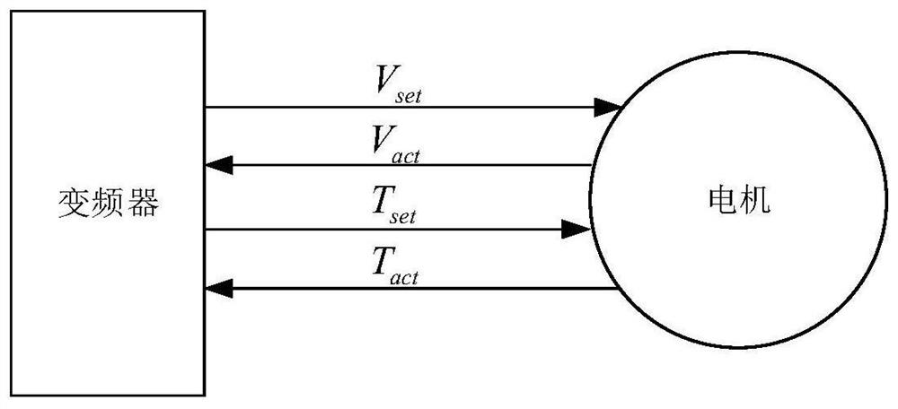
[0017] The embodiment of the present invention also provides a computer device to solve the technical problem in the prior art that the transfer function derived from the built-in parameters of the frequency converter is used to control the work of the rod and wire mill, so that the actual speed of the rod and wire mill has a large deviation. The computer equipment includes a memory, a processor, and a computer program stored in the memory and operable on the processor. When the processor executes the computer program, the above method for fitting the steady-state value of the rotational speed of a rod and wire rolling mill is realized.

Method used


Image

  • Rotation speed steady-state value fitting method and device for ball-wire mill
  • Rotation speed steady-state value fitting method and device for ball-wire mill
  • Rotation speed steady-state value fitting method and device for ball-wire mill

Examples


Embodiment Construction

[0032] In order to make the purpose, technical solutions and advantages of the embodiments of the present invention more clear, the embodiments of the present invention will be further described in detail below in conjunction with the accompanying drawings. Here, the exemplary embodiments and descriptions of the present invention are used to explain the present invention, but not to limit the present invention.

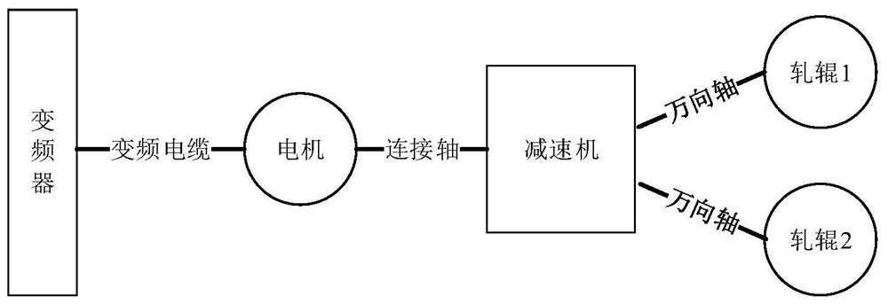
[0033] Usually, multiple rolling mills are set up on the hot continuous rolling production line of rods and wires, and each rolling mill works according to a given speed and torque. The rotation speed of each rolling mill in the hot continuous rolling production line is different. From the first rolling mill to the last rolling mill, the rotating speed is getting higher and higher, so that there will be no accumulation in the process of moving the billet from the first rolling mill to the last rolling mill , affecting the work of the entire production line.

[0034] ...


PUM


Abstract

The invention discloses a rotation speed steady-state value fitting method and device for a ball-wire mill, and the method comprises the steps: controlling a set rotation speed value of the ball-wiremill to rise or fall to a target rotation speed value in a process that the ball-wire mill works according to the set rotation speed value, and enabling the actual rotation speed value of the ball-wire mill to present a step response process; acquiring an actual rotation speed value of the ball-wire mill in a stable stage; fitting the actual rotation speed value of the ball-wire mill in the stablestage into a straight line in a coordinate system which takes time as horizontal coordinates and takes the rotation speed as vertical coordinates; determining an longitudinal axis intercept value ofthe straight line as an actual rotation speed steady-state value of the ball-wire mill in the steady stage. The accuracy of transfer function parameter identification can be improved, so that a transfer function which conforms to the actual rotation speed of the ball-wire mill better is obtained, and the ball-wire mill is controlled to work, and thus, the situation that bars and wires on the millare accumulated is effectively prevented, and the bar and wire production efficiency is improved.

Description

technical field [0001] The invention relates to the field of rolling mill control, in particular to a method and device for fitting the steady-state value of the rotational speed of a bar and wire rolling mill. Background technique [0002] This section is intended to provide a background or context to embodiments of the invention that are recited in the claims. The descriptions herein are not admitted to be prior art by inclusion in this section. [0003] The continuous hot rolling production line of rods and wires refers to the way of physical deformation, so that the thick and short steel billets are continuously squeezed to form thin and long steel products. [0004] Before the steel billet is sent to the rod and wire rod hot rolling production line, the steel billet needs to be heated. The steel slab at room temperature is moved to the heating furnace through the walking beam, and the heating furnace uses coal gas or natural gas to heat the slab. In the heating furna...

Claims


Application Information

Patent Timeline
IPC IPC(8): B21B37/46
CPCB21B37/46
Inventor 刘东李铁王云波
Owner MCC CAPITAL ENGINEERING & RESEARCH
Learn More