AI technical title is built by PatSnap AI team. It summarizes the technical point description of the patent document.
A cutting machine, mobile technology, applied in the direction of hand-held metal shearing equipment, shearing devices, manufacturing tools, etc., can solve the problem of affecting cutting speed and cutting quality, difficult to fully observe and operate, difficult to cut position alignment, etc. Problems, to achieve the effect of easy cutting operation, convenient observation and positioning, and prevent damage
Active Publication Date: 2022-02-11
XINXING DUCTILE IRON PIPES CO LTD
View PDF0 Cites 0 Cited by
Summary
Abstract
Description
Claims
Application Information
AI Technical Summary
This helps you quickly interpret patents by identifying the three key elements:
Problems solved by technology
Method used
Benefits of technology
Problems solved by technology
The problem with this type of product is that it is not adaptable enough and the scope of application is too narrow
[0004] On the other hand, if the moving handle and the cutting handle need to be controlled separately by hand at the same time, the labor load of the person is large, and the moving speed of the cutting bracket is different if the strength of the person controlling the moving handle is different. Experience control strength, not the same as control movement speed
[0005] In addition, the existing movable cutting machine is difficult to align the cutting position while stabilizing the base of the cutting machine; it is also difficult to observe whether the cutting position is appropriate from a suitable angle during cutting, often from the rear The cutting position, if viewed from both sides of the cutting position, the selected base is often not stable enough, which makes it difficult to fully observe and operate, which eventually leads to increased labor intensity and affects cutting speed and cutting quality at the same time
Method used
Image
Click on the blue label to locate the original text in one second.
Reading with bidirectional positioning of images and text.
Examples
Embodiment Construction
[0035] Below in conjunction with embodiment the present invention is described in further detail:
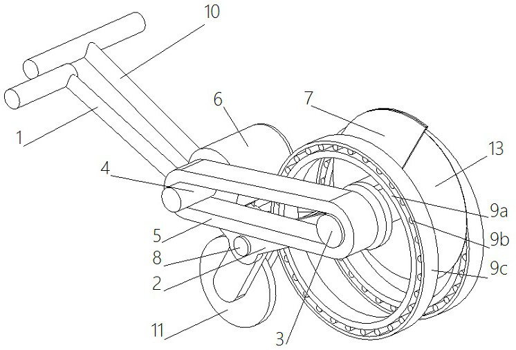
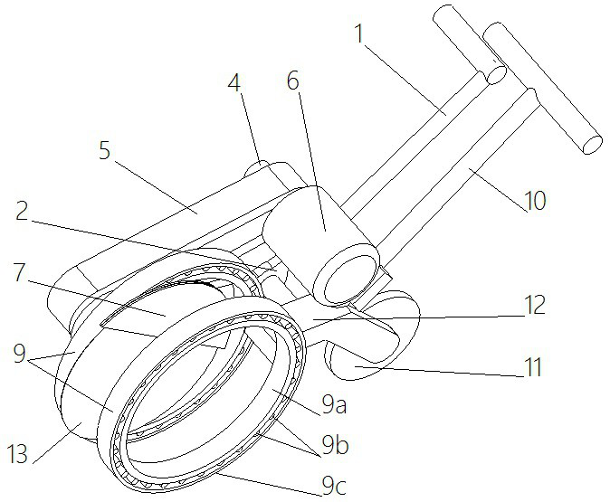
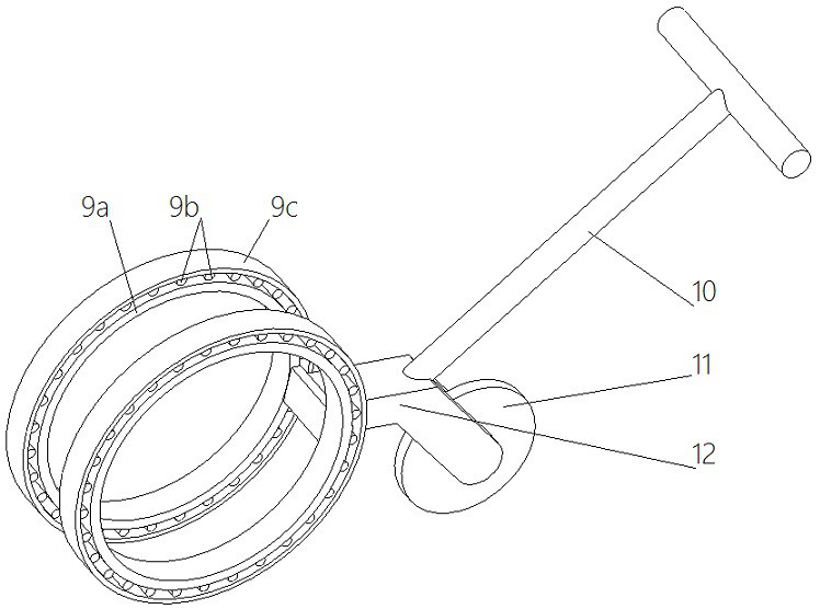
[0036] Such as figure 1 , figure 2 , image 3 , Figure 4 Shown, a kind of movable cutting machine comprises frame 2, cutter shaft 3, motor pulley 4, belt 5, motor 6 fixed on the frame 2, cutting blade 13, sleeved on the outside of cutting blade 13 Shield 7 also comprises traveling vehicle, and all devices of original cutting machine are all arranged on the traveling vehicle. Walking cart comprises vehicle frame 12, hubless wheel 9, cart handle 10, walking wheel 11, and hubless wheel 9 is symmetrically arranged on vehicle frame 12 front ends, and hubless wheel 9 is hollow setting, and hubless wheel 9 is provided with two. The cart handle 10 is fixedly connected on the vehicle frame 12, and the traveling wheels 11 are hinged at the rear of the vehicle frame 12; the frame 2 is also provided with a frame hinge point 8 and a cutting machine handle 1, and the frame hinge point 8...
PUM
Abstract
The invention discloses a movable cutting machine, which relates to the technical field of cutting, and comprises a frame, a cutting machine shaft, a motor pulley, a belt, a motor fixed on the frame, a cutting piece, and a shield sleeved on the outside of the cutting piece , also includes a trolley, the trolley includes a vehicle frame, two hollow hubless wheels symmetrically arranged at the front end of the vehicle frame, a cart handle fixedly connected to the vehicle frame, and a walking wheel hinged at the rear of the vehicle frame; The frame is also provided with a frame hinge point hinged on the vehicle frame, a cutter handle is also provided on the frame, and the frame extends from one side of the vehicle frame to the front. The shaft of the cutting machine passes through one hubless wheel, and the cutting piece is arranged in the gap between the two hubless wheels. The invention facilitates the observation and positioning of the cutting, facilitates the cutting operation, reduces labor intensity, and improves the cutting efficiency. Quality, improved cutting accuracy, accelerated cutting speed, improved safety, and improved the scope of application of cutting equipment.
Description
technical field [0001] The invention relates to the technical field of cutting, in particular to a movable cutting machine. Background technique [0002] At present, most of the cutting machines in the market are fixed, which cannot be used when cutting large-sized steel gratings. However, there are many small-sized step plates in the market, and there is an urgent need for fast cutting instead of slow flame cutting. To improve production efficiency, improve labor efficiency and reduce production costs. At present, electric cutting tools are widely used in the field of mechanical processing and manufacturing. A relatively common electric tool is a cutting machine, which can be used to cut stone workpieces such as marble, ceramic tiles, and hollow bricks. For ease of cutting, sink cutters are usually fitted with a movable head. The head of the existing cutting machine can move relative to the workbench, but parts such as guide rails are often worn during the moving process...
Claims
Application Information
Patent Timeline
Application Date:The date an application was filed.
Publication Date:The date a patent or application was officially published.
First Publication Date:The earliest publication date of a patent with the same application number.
Issue Date:Publication date of the patent grant document.
PCT Entry Date:The Entry date of PCT National Phase.
Estimated Expiry Date:The statutory expiry date of a patent right according to the Patent Law, and it is the longest term of protection that the patent right can achieve without the termination of the patent right due to other reasons(Term extension factor has been taken into account ).
Invalid Date:Actual expiry date is based on effective date or publication date of legal transaction data of invalid patent.

