Automatic feeding device for small bearings
A technology of automatic feeding and feeding device, used in transportation and packaging, conveyor objects, conveyors, etc., can solve the problems of loud motor noise, bad bearing sound, low production efficiency, etc., to save the transfer structure and simplify the feeding. material process, to achieve the effect of full automation
- Summary
- Abstract
- Description
- Claims
- Application Information
AI Technical Summary
Problems solved by technology
Method used
Image
Examples
Embodiment 1
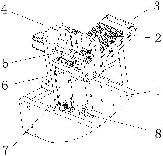
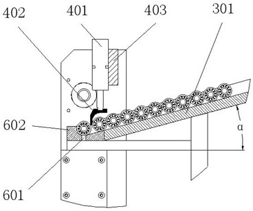
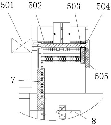
[0026] as attached Figure 1-5 As shown, Embodiment 1 of the present invention provides an automatic loading and feeding device for small bearings, including a frame body 1 of the device, on which a storage bin 3 is fixed, and the storage bin 3 is an open box Type structure (openable transparent cover can also be added on top), the bottom plate of the silo is set as a slope 301, and the inclination angle of the slope 301 is 1°<α<45°; a large number of bearings 2 are installed in the storage silo 3, and when feeding, the bearings 2 Start from the bearing transfer rail 6 below the silo 3 and place them neatly in the storage silo 3 row by row, column by column, and radially along the slope of the silo; assuming that the thickness of the bearing 2 is T, the bearings placed in each row The number is n, then the inner width L of the bearing placed in bin 3 needs to satisfy nT<L<1.5nT.
[0027] The limit stop mechanism 4 is fixed on the top of the storage bin 3, including a cylinder...
Embodiment 2
[0034] as attached Image 6As shown, Embodiment 2 of the present invention provides an automatic feeding device for small bearings. The main structure is roughly the same as Embodiment 1, including a storage bin A, a limit stop mechanism B, a drive linkage mechanism C, Bearing transfer material track D, bearing press-fitting pre-waiting material channel warehouse E.
[0035] Wherein, the drive link mechanism C is composed of a cylinder C1, a drive link C2, two guide posts C3 and a mounting plate C4 / C5. The cylinder C1 is horizontally fixed on the mounting plate C4, and the push rod of the cylinder is set directly above the bearing transfer material rail D; the two guide columns C3 are horizontally fixed on the mounting plate C4 / C5, and are set on both sides of the push rod of the cylinder C1. Stay parallel to the putter. The end of the cylinder push rod is fixedly connected with the drive connecting rod C2, and a through hole or guide sleeve is arranged at each end of the dr...
PUM
 Abstract
Description
Claims
Application Information
 - R&D
- Intellectual Property
- Life Sciences
- Materials
- Tech Scout
- Unparalleled Data Quality
- Higher Quality Content
- 60% Fewer Hallucinations
Browse by: Latest US Patents, China's latest patents, Technical Efficacy Thesaurus, Application Domain, Technology Topic, Popular Technical Reports.
© 2025 PatSnap. All rights reserved.Legal|Privacy policy|Modern Slavery Act Transparency Statement|Sitemap|About US| Contact US: help@patsnap.com


