Textile compressor capable of packaging

A compressor and textile technology, applied in packaging and other directions, can solve the problems of affecting the effect of compression, trouble, shorten the service life of hydraulic compressors, etc., and achieve the effect of high compression efficiency

Inactive Publication Date: 2021-02-09
诸暨市惠联精密机械制造有限公司
View PDF14 Cites 1 Cited by
  • Summary
  • Abstract
  • Description
  • Claims
  • Application Information

AI Technical Summary

Problems solved by technology

After the compressor finishes compressing the fluffy cotton and plush, the staff will usually pack and seal them immediately. During this period, the cotton and plush will become fluffy again, which will affect the compression effect. If the packaging requirements cannot be met , it is necessary to continue to compress until the cotton and plush meet the packaging requirements after repeated compression
Usually cotton, plush, etc. often need to be compressed several times to achieve a satisfactory packaging effect, which not only consumes time and energy, but also shortens the service life of the hydraulic compressor, resulting in an increase in the maintenance cost of the compressor.
[0003] The traditional textile compressor has some disadvantages. Generally, the fabric is first packed into bags, and then the bagged fabric is compressed and packaged. The previous compression method needs to manually connect the bag to the suction device, which is inefficient. When packing vacuum fabrics, the staff needs to support the opening of the bag, which is troublesome

Method used


Image

  • Textile compressor capable of packaging
  • Textile compressor capable of packaging
  • Textile compressor capable of packaging

Examples


Embodiment Construction

[0030]The following description is used to disclose the present invention so that those skilled in the art can implement the present invention. The preferred embodiments in the following description are only examples, and those skilled in the art can think of other obvious variations.

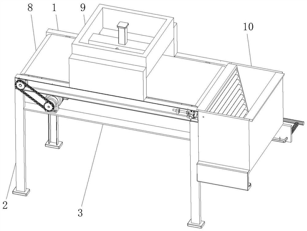
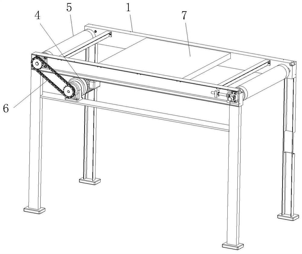
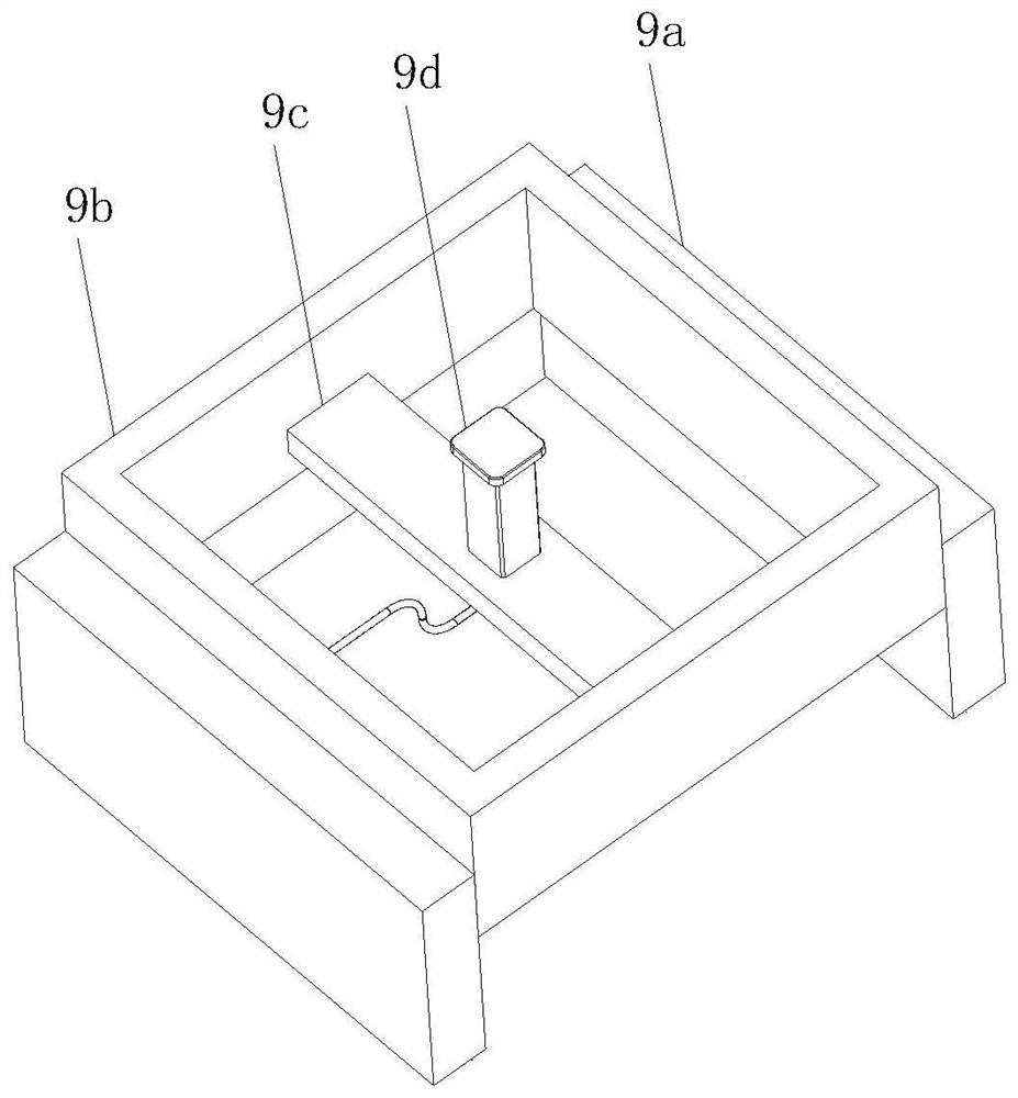
[0031]SeeFigure 1-9, A textile compressor that can be packaged, including a base conveying body 1, a supporting foot 2 is provided at the lower end of the conveying body 1, a mounting plate 3 is fixedly mounted on the inner side of the supporting foot 2, and a driving motor is fixedly mounted on the upper end of the mounting plate 3 4. The inner side of the conveying body 1 is provided with a rotating drum 5, a transmission mechanism 6 is arranged between the driving motor 4 and the rotating drum 5, and the inner side of the conveying body 1 is fixedly installed with a support plate 7 on the side close to the rotating drum 5, the rotating drum 5 A conveyor belt 8 is provided on the outside of the suppor...


PUM


Abstract

The invention relates to the technical field of textile compressors, in particular to a textile compressor capable of packaging. The textile compressor comprises a base conveying body, wherein supporting legs are arranged at the lower end of the conveying body; a mounting plate is fixedly arranged at the inner sides of the supporting legs; a driving motor is fixedly arranged at the upper end of the mounting plate; a rotary drum is arranged at the inner side of the conveying body; a transmission mechanism is arranged between the driving motor and the rotary drum; a supporting plate is fixedly arranged at the side, close to the rotary drum, of the inner side of the conveying body; a conveyor belt is arranged at the outer side of the rotary drum and the outer side of the supporting plate; a compression mechanism is arranged over the portion, close to the supporting plate, of the upper end of the conveying body; a discharging frame is arranged at one end of the conveying body; a material guiding mechanism is arranged in the discharging frame; and a supporting framework is arranged at the lower end of the discharging frame. According to the textile compressor capable of packaging, the textile compression efficiency can be improved, a packing bag does not need to be opened manually in the textile packaging process, and the textile compressor is practical.

Description

Technical field[0001]The invention relates to the technical field of textile compressors, in particular to a textile compressor that can be packaged.Background technique[0002]Compressor is a very widely used textile industry machinery. In the textile industry, compressors are often used to compress fluffy cotton, wool, and cashmere. Compressors are mainly divided into manual compressors and mechanical compressors. Manual compressors are currently only used by small workshops due to low efficiency and waste of manpower. The most widely used in most textile companies is the mechanical compressor, and the most commonly used mechanical compressor is the hydraulic compressor. After the compressor has compressed the fluffy cotton and fluff, usually the staff will pack and seal immediately. During this time, the cotton and fluff will be fluffy again, which affects the compression effect. If the packaging requirements are not met , It is necessary to continue to compress until the cotton an...

Claims


Application Information

Patent Timeline
Patent Type & Authority Applications(China)
IPC IPC(8): B65B63/02B65B43/26
CPCB65B43/26B65B63/028
Inventor 边疆
Owner 诸暨市惠联精密机械制造有限公司
Why Eureka
Try Eureka