Impeller device and turbine flowmeter

An impeller and shaft technology, applied in the field of turbine flowmeters, can solve the problems of reduced sensitivity and accuracy of turbine flowmeters, and achieve the effects of improving sensitivity, reducing maintenance costs, and increasing the measurement range

Pending Publication Date: 2020-09-29
隆昌市力佳商贸有限公司
View PDF0 Cites 0 Cited by
  • Summary
  • Abstract
  • Description
  • Claims
  • Application Information

AI Technical Summary

Problems solved by technology

[0004] The purpose of the present invention is to provide an impeller device and a turbine flowmeter for the problem that the fluid in the existing turbine flowmeter in the prior ar

Method used


Image

  • Impeller device and turbine flowmeter
  • Impeller device and turbine flowmeter
  • Impeller device and turbine flowmeter

Examples


Embodiment 1

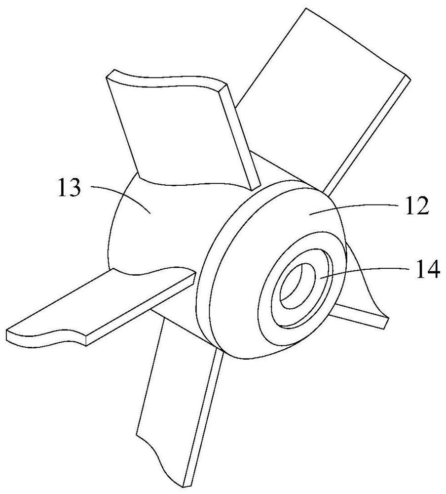
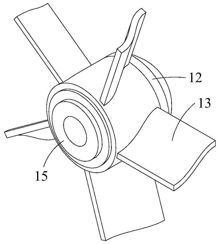
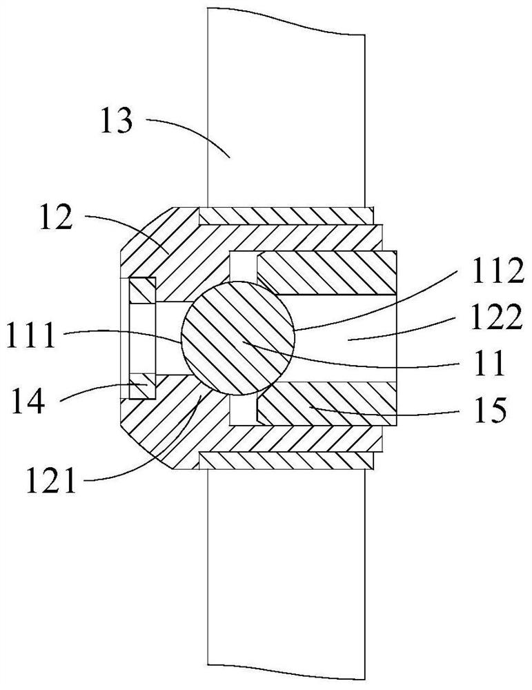
[0067] like Figure 1-4 As shown, an impeller device described in this embodiment includes an impeller assembly 1, a second rotating shaft 2 and a first rotating shaft 3, the impeller assembly 1 can rotate around the first rotating shaft 3, and the second rotating shaft 2 and the first rotating shaft 3 are coaxially arranged, the impeller assembly 1 is located between the second rotating shaft 2 and the first rotating shaft 3, the end of the second rotating shaft 2 and the end of the first rotating shaft 3 Both parts are capable of 1-point contact with the impeller assembly.

[0068] Specifically, the impeller assembly 1 includes a rotating sleeve 12 and an impeller structure 13 sleeved on the outside of the rotating sleeve 12. The rotating sleeve 12 and the impeller structure 13 are tightly fitted, that is, the rotating sleeve 12 and the The impeller structure 13 can rotate integrally. When dismounting or installing, a certain external force must be applied to make the two m...

Embodiment 2

[0087] like Figure 5-16 As shown, the present invention also discloses a turbine flowmeter, including a cylinder body 5 and the impeller device as described in Embodiment 1, the first rotating shaft 3 and the cylinder body 5 are connected through a first cage 6, The second rotating shaft 2 and the cylinder body 5 are connected through the second cage 4 , and the first cage 6 , the second cage 4 and the impeller assembly are all arranged in the cylinder body 5 .

[0088] The first cage 6 is specifically: the first cage 6 is provided with a first through hole 61 axially along the first rotating shaft 3 , and the first through hole 61 has a first threaded hole 612 and a first mounting hole 611 , the first mounting hole 611 is located on the side of the first threaded hole 612 close to the impeller assembly 1, the first mounting hole 611 is matched with the first rotating shaft 3, and the first cage 6 A first plug 62 for closing the end of the first through hole 61 is provided o...


PUM


Abstract

The invention relates to a turbine flowmeter, particularly to an impeller device and a turbine flowmeter. The impeller device comprises an impeller assembly and a first rotating shaft, wherein the impeller assembly can rotate around the first rotating shaft, and the end of the first rotating shaft abuts against the impeller assembly and makes point contact with the impeller assembly. According tothe impeller device, when the impeller assembly rotates, the frictional resistance of the impeller device is smaller than that of an existing turbine flow meter, so that the metering sensitivity of the impeller device is high, and the minimum value capable of being metered is small so as to widen the metering range of the turbine flow meter.

Description

technical field [0001] The invention relates to a turbine flowmeter, in particular to an impeller device and a turbine flowmeter. Background technique [0002] At present, the turbine flowmeter is composed of a turbine and an external detection pulser. The fluid flows into the turbine to cause the rotor to rotate. The specific inner diameter makes the rotor speed directly proportional to the flow. The detection pulser converts the detected rotor blade rotation into a pulse signal proportional to the flow rate, and then into a flow display signal to record the flow rate. The rotor rotates relative to the cylinder through the bearings at both ends, which has good repeatability. With the advantages of simple structure, small size, simple operation and convenient maintenance, it can be widely used in petroleum, chemical industry, metallurgy, organic fluid, inorganic liquid, liquefied petroleum gas, urban gas pipeline network, pharmaceutical, food, papermaking, etc. [0003] How...

Claims


Application Information

Patent Timeline
IPC IPC(8): G01F1/32G01F15/00G01F15/18
CPCG01F1/32G01F15/00G01F15/18
Inventor 李怀东
Owner 隆昌市力佳商贸有限公司
Why Eureka
Try Eureka