
Device and method for dismounting and recovering steel coil binding belt by robot

A recycling device and robot technology, applied in transportation and packaging, packaging, binding material removal, etc., can solve the problems of irregular shape, robot damage, high labor intensity, etc., achieve the same curling shape of the straps, and reduce strict requirements , the effect of improving work efficiency

Active Publication Date: 2021-02-09
BEIJING SHOUGANG AUTOMATION INFORMATION TECH
View PDF6 Cites 1 Cited by
  • Summary
  • Abstract
  • Description
  • Claims
  • Application Information

AI Technical Summary

Problems solved by technology

[0002] With the continuous improvement of living standards, household appliances and automobiles have become the necessities of people's life, and the demand for cold-rolled plates as one of the main raw materials has also reached a high point. The belt removal operation is mainly done manually. The working area is highly dangerous and labor intensive. It is a repetitive work. Some steel plants have adopted some kind of robot belt removal and belt collection device. The method of removing the belt is to use a hydraulic The cylinder drives the steel shovel to scoop up the strap on one side and press it between the steel shovel and the stopper on one side, and the other hydraulic cylinder drives the scissors to cut the strap
[0003] When the existing strap is shoveled, due to the unilateral force, the strap will generate a reaction torque to the end effector of the unbundling strap, and the reaction torque will be transmitted to the robot, causing certain damage to the robot, and also Make the end effector of the unbundling belt bear a lot of force. In order to overcome this shortcoming, it is necessary to choose a robot with a larger load, increase the mechanical strength of the end effector of the unbundling belt, and increase the mechanical strength of the end effector of the unbundling belt, and the robot and the end effector of the unbundling belt A buffer device is added between them, and a hydraulic cylinder with a stronger driving capacity is used to drive the steel shovel and scissors. The steel shovel moves in an oblique downward direction during the process of shovel binding, which requires accurate positioning of the steel shovel’s descending position and trajectory. Too early or too late will not be able to shovel the strap smoothly, and even damage the steel coil itself. In order to accurately locate the position, it is necessary to add a high-precision sensor to detect the position of the strap, and repeatedly teach the robot to find a suitable falling trajectory. The change in the tightness of the coil strap itself, that is, the size of the gap between the strap and the surface of the steel coil, will also affect the success rate of the shovel strap
The matching strap collecting device uses a motor to drive the steel fork to roll the removed strap first, and then presses it tightly with a hydraulic cylinder. The disadvantage is that the length of the strap with the motor and the steel fork is different. , although the overall shape is long after compression, the shape is irregular, and there is more space for collection. At the same time, severe plastic deformation occurs after the strap is flattened, and the strap cannot be reused.

Method used


Image

  • Device and method for dismounting and recovering steel coil binding belt by robot
  • Device and method for dismounting and recovering steel coil binding belt by robot
  • Device and method for dismounting and recovering steel coil binding belt by robot

Examples


Embodiment Construction

[0038] The preferred embodiments of the present invention will be described below in conjunction with the accompanying drawings. It should be understood that the preferred embodiments described here are only used to illustrate and explain the present invention, and are not intended to limit the present invention.

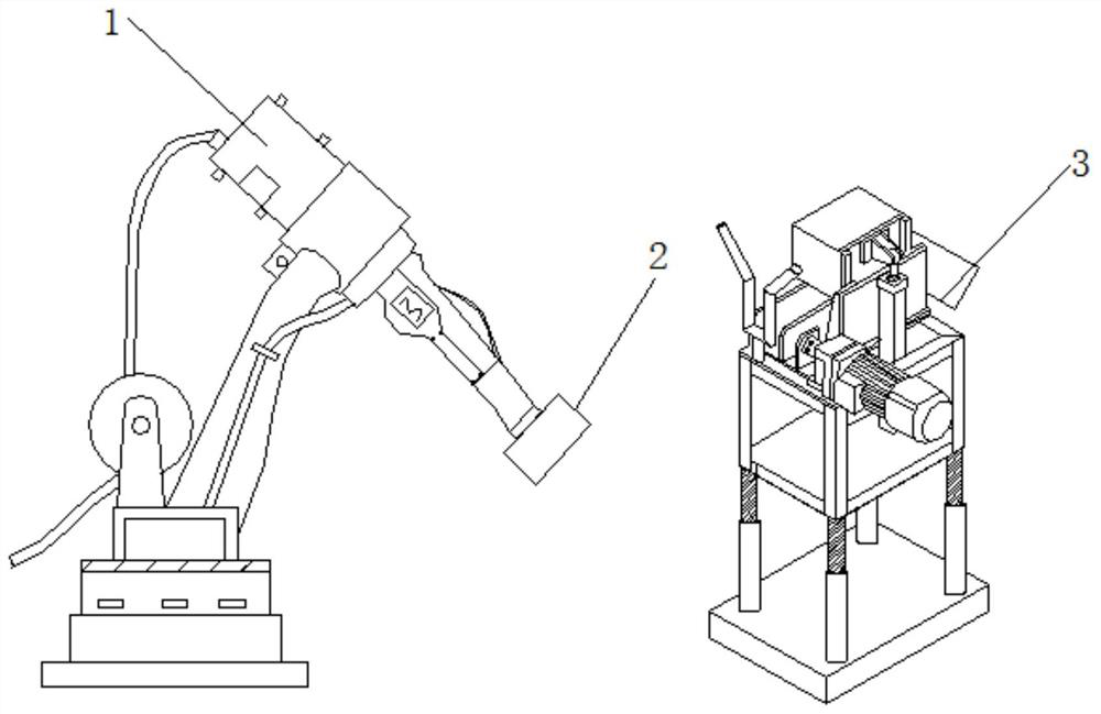
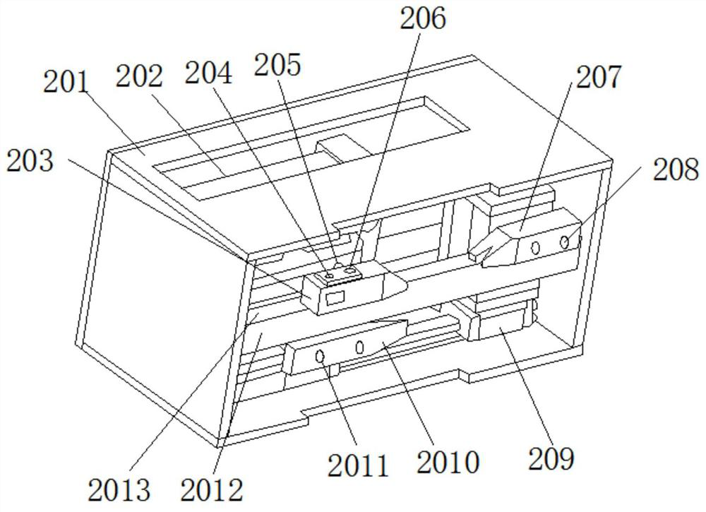
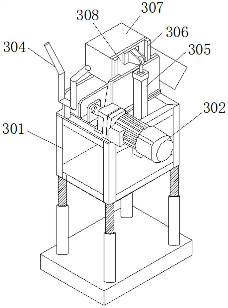
[0039] Such as Figure 1-Figure 5As shown, a robot steel coil strap removal and recovery device includes a robot body 1, and an end actuator 2 is installed on one side of the robot body 1, and there is no It includes a housing 201 fixedly connected to one end of the robot body 1, and a linear guide rail 1 209 is fixedly connected to one side of the inner wall of the housing 201, the linear guide rail 1 209 slider 1 is fixedly connected to the cylinder 202, and one end of the cylinder 202 is fixed The guide rod two 2011 is connected, and the other end of the guide rod two 2011 is fixedly connected with scissors 2010, the guide rod 2012 is fixed to the housing, and th...


PUM


Abstract

The invention relates to a device for dismounting and recovering a steel coil binding belt by a robot. The device for dismounting and recovering the steel coil binding belt by the robot comprises a robot body, wherein a binding belt dismounting end executor is installed at one side of the robot body; a shell body fixedly connected with one end of the robot body is not included in the binding beltdismounting end executor, and a linear guide rail I is fixedly connected to one side of the inner wall of the shell body; and the linear guide rail I is fixedly connected with the an air cylinder I. According to the invention, a binding belt is located at any position between two clamps, strict requirements on locating and motion tracks of the end executor are reduced, meanwhile, when the bindingbelt is shoveled up, two sides of the binding belt are shoveled up at the same time, and the binding belt dismounting end executor is uniformly stressed and does not bear an overlarge torque; and dovetail groove designs at the end parts of the clamps can also accurately locate the position of the shoveled binding belt to adapt to the change of the tightness of the binding belt, the clamp at the side where scissors are located, adopts an air spring, the action of clamping the binding belt at first, and then shearing the binding belt can be realized, and in this way, the process of shearing after clamping can be completed by one-time action of the air cylinder, and the working efficiency is increased.

Description

technical field [0001] The invention relates to a robot steel coil strap removal and recovery device and method thereof, and belongs to the technical field of robot steel coil strap removal and recovery. Background technique [0002] With the continuous improvement of living standards, household appliances and automobiles have become the necessities of people's life, and the demand for cold-rolled plates as one of the main raw materials has also reached a high point. The belt removal operation is mainly done manually. The working area is highly dangerous and labor intensive. It is a repetitive work. Some steel plants have adopted some kind of robot belt removal and belt collection device. The method of removing the belt is to use a hydraulic The cylinder drives the steel shovel to scoop up the strap on one side and press it between the steel shovel and the stopper on one side, and the other hydraulic cylinder drives the scissors to cut the strap. [0003] When the existing ...

Claims


Application Information

Patent Timeline
Patent Type & Authority Applications(China)
IPC IPC(8): B65B69/00
CPCB65B69/0025
Inventor 张雪成王辉王洪庚任鹏举
Owner BEIJING SHOUGANG AUTOMATION INFORMATION TECH
Learn More