Displacement sensor steel wire rope vertical wire outlet device
A displacement sensor and wire rope technology, applied in the field of displacement sensor wire rope vertical outlet, can solve the problems of reducing the retraction speed of the wire rope, the wire rope is easy to damage the displacement sensor, etc., and achieve the effect of avoiding position dislocation
- Summary
- Abstract
- Description
- Claims
- Application Information
AI Technical Summary
Problems solved by technology
Method used
Image
Examples
Embodiment 1
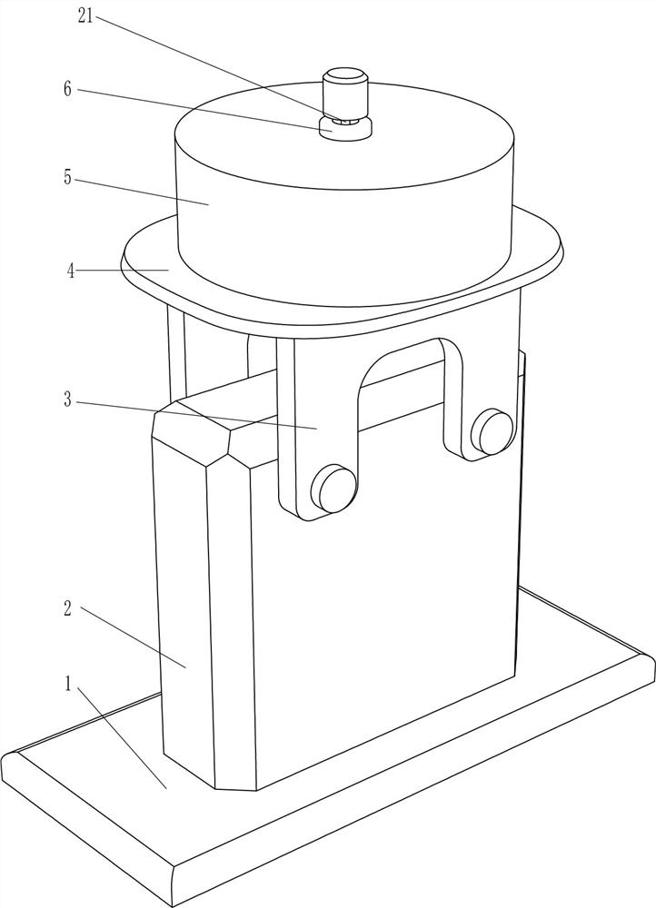
[0046] A vertical wire rope outlet for displacement sensors, such as figure 1 As shown, it includes a base 1, a displacement sensor 2, a support frame 3, a support plate 4, a hollow cylinder 5, a rope outlet ring 6 and a vertical device 7, a displacement sensor 2 is connected in the middle of the base 1, and a steel wire rope 21 is placed inside the displacement sensor 2. Displacement sensor 2 is connected with support frame 3 on the front and rear sides, support plate 4 is connected between support frame 3 tops, support plate 4 top is connected with hollow tube 5, hollow tube 5 top middle is connected with rope ring 6, support plate 4 The top is connected with a vertical device 7, the vertical device 7 is located in the hollow tube 5, and the steel wire rope 21 passes through the displacement sensor 2, the support plate 4, the hollow tube 5 and the vertical device 7.
[0047] When people need to use the steel wire rope 21, people move the steel wire rope 21 vertically upwards...
Embodiment 2
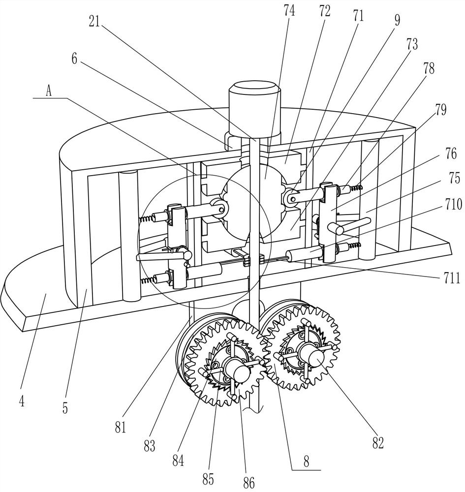
[0049] On the basis of Example 1, such as figure 2 and Figure 4 As shown, the vertical device 7 includes a spacer 71, an upper cover plate 72, a lower cover plate 73, a roller core 74, a fixed frame 75, a rotating shaft 76, a torsion spring 77, a sliding column 78, a return spring 79, a sliding shaft 710, a pull rod 711 and limit ring 712, the middle of the top of the support plate 4 is connected with a spacer 71, the spacer 71 is located in the hollow tube 5, the upper side of the spacer 71 is connected with the upper cover plate 72, and the lower side of the spacer 71 is connected with the lower cover Plate 73, the upper cover plate 72 and the lower cover plate 73 are rotatably connected with a roller core 74, and the steel wire rope 21 passes through the roller core 74, the upper cover plate 72 and the lower cover plate 73, and the front, rear, left, and right sides of the top of the support plate 4 are all connected. There is a fixed frame 75, and the fixed frame 75 is ...
Embodiment 3
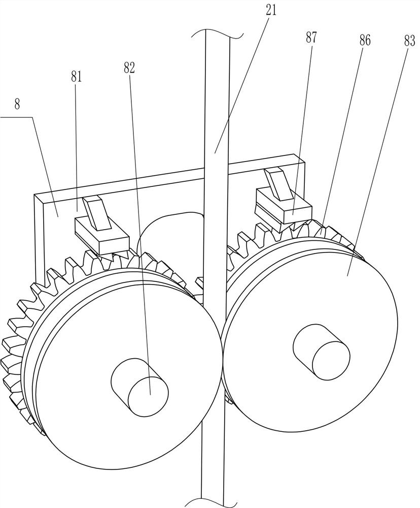
[0052] On the basis of Example 2, such as Figure 2-4 As shown, a speed reduction device 8 is also included, and the speed reduction device 8 includes a support block 81, a fixed shaft 82, a sheave 83, a ratchet 84, a mounting frame 85, a gear 86 and a ratchet 87, and the front and rear sides in the middle of the bottom of the support plate 4 Both are connected with support blocks 81, and the left and right sides between the support blocks 81 are connected with fixed shafts 82 in a rotational manner, and the rear sides of the fixed shafts 82 are connected with a rope pulley 83, and the steel wire rope 21 is located between the rope pulleys 83, and the fixed shaft 82 The front side is connected with a ratchet 84, and the front side of the fixed shaft 82 is rotatably connected with a mounting frame 85. The mounting frame 85 is located at the front side of the fixed shaft 82. meshing, the gears 86 are meshed with each other, and the upper and rear sides of the support block 81 on...
PUM
 Abstract
Description
Claims
Application Information
 - R&D
- Intellectual Property
- Life Sciences
- Materials
- Tech Scout
- Unparalleled Data Quality
- Higher Quality Content
- 60% Fewer Hallucinations
Browse by: Latest US Patents, China's latest patents, Technical Efficacy Thesaurus, Application Domain, Technology Topic, Popular Technical Reports.
© 2025 PatSnap. All rights reserved.Legal|Privacy policy|Modern Slavery Act Transparency Statement|Sitemap|About US| Contact US: help@patsnap.com


