Road flatness detection device

A detection device and flatness technology, applied in the field of road detection and road flatness detection, can solve the problems of inability to monitor the road surface flatness in real time, and inability to detect road deformation, and achieve the effect of high accuracy

Active Publication Date: 2021-02-09
日照市市政工程质量检测有限公司
View PDF7 Cites 0 Cited by
  • Summary
  • Abstract
  • Description
  • Claims
  • Application Information

AI Technical Summary

Problems solved by technology

[0008] The object of the invention of the present invention is: to solve the above problems, provide a road roughness detection device, by laying optical fiber in the road, real-time detection of light reflection in the optical fiber to judge the change of the road surface roughness, and the original database Comparing and judging, accurately

Method used


Image

  • Road flatness detection device
  • Road flatness detection device

Examples


Embodiment Construction

[0031] All features disclosed in this specification, or steps in all methods or processes disclosed, may be combined in any manner, except for mutually exclusive features and / or steps.

[0032] Any feature disclosed in this specification (including any appended claims, abstract), unless otherwise stated, may be replaced by alternative features which are equivalent or serve a similar purpose. That is, unless expressly stated otherwise, each feature is one example only of a series of equivalent or similar features.

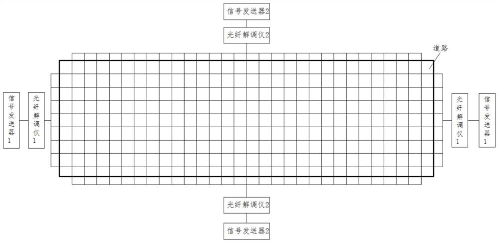
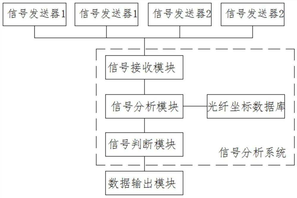
[0033] Such as figure 1 with figure 2 As mentioned above, the road smoothness detection device of the present invention is respectively laid with optical fibers in the vertical and horizontal directions in the road, and the optical fibers laid in the road are respectively arranged in a network shape along the horizontal and vertical directions; the optical fibers are arranged parallel to each other in the longitudinal direction, so that The optical fibers are arr...


PUM


Abstract

The invention discloses a road flatness detection device, and belongs to the field of road detection. Optical fibers are laid in the longitudinal direction and the transverse direction in a road respectively, the two ends of each optical fiber are connected with an optical fiber demodulator respectively, and the optical fiber demodulator transmits and receives spectral signals into the optical fibers; the optical fiber demodulator is in signal connection with a signal transmitter and transmits the received spectral signal to the signal transmitter; the signal transmitter is connected with a signal analysis system and converts spectral signals into corresponding optical fiber label signals and transmits the optical fiber label signals to a signal analysis system, and the signal analysis system correspondingly analyzes the optical fiber label signals and an optical fiber coordinate system and judges coordinate values corresponding to spectral signal changes/non-spectral signals; and thesignal analysis system is connected with a data output unit and transmits coordinate value data to the data output unit. According to the invention, the optical fibers are laid in the road, change ofthe road surface flatness is judged by detecting the light reflection condition in the optical fiber in real time, and the road surface deformation point/area is accurately found.

Description

technical field [0001] The invention relates to the technical field of road detection, in particular to the technical field of road roughness detection. Background technique [0002] After the road paving is completed, due to terrain settlement, deformation, rain erosion, vehicle driving, heavy rolling, etc., it is easy to cause deformation of the roadside, forming pits or bulges, etc., causing road deformation, which in turn affects the safety of road driving , especially roads such as airport runways, racing tracks, and experimental roads, have extremely high requirements for the smoothness of the road; therefore, it is necessary to test the smoothness of the road for a long time. [0003] At present, the methods of road roughness detection include: [0004] 1. The traditional 3M ruler detection method is to place a 3-meter-long ruler on the road and check the fit between the ruler and the road surface to judge the smoothness of the road surface. This method can only jud...

Claims


Application Information

Patent Timeline
IPC IPC(8): E01C23/01
CPCE01C23/01
Inventor 不公告发明人
Owner 日照市市政工程质量检测有限公司
Why Eureka
Try Eureka