Energy-saving irrigation device for water conservancy project

A technology for water conservancy projects and irrigation devices, which is applied to watering devices, spraying devices, devices for catching or killing insects, etc. It can solve the problems of cumbersome operation, control of irrigation time, and inability to move anytime and anywhere, and achieve a simple and stable structure. , highly universal effect

Inactive Publication Date: 2022-01-28
河南基安建设集团有限公司
View PDF0 Cites 0 Cited by
  • Summary
  • Abstract
  • Description
  • Claims
  • Application Information

AI Technical Summary

Problems solved by technology

[0009] In view of the above situation, in order to overcome the defects of the prior art, the present invention provides an energy-saving irrigation device for water conservancy projects, which effectively solves the problem that the existing drip irrigation and sprinkler irrigation devices need to lay pipes in a large area, cannot be moved anytime and anywhere, and the operation is cumbersome and impossible. The problem of controlling irrigation time according to soil moisture conditions

Method used


Image

  • Energy-saving irrigation device for water conservancy project
  • Energy-saving irrigation device for water conservancy project
  • Energy-saving irrigation device for water conservancy project

Examples


Embodiment 1

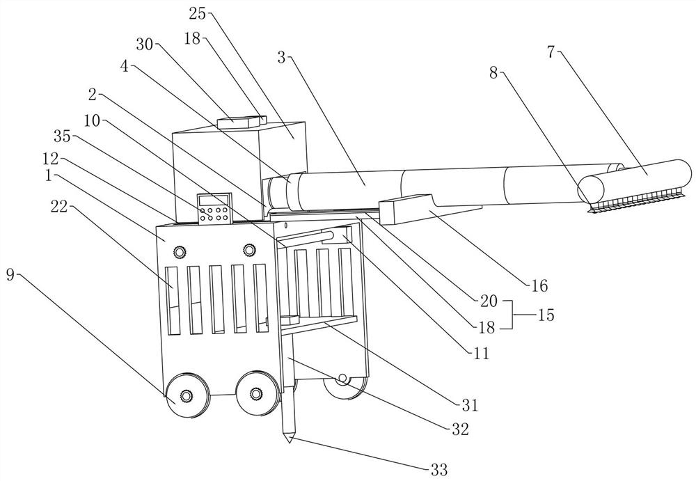
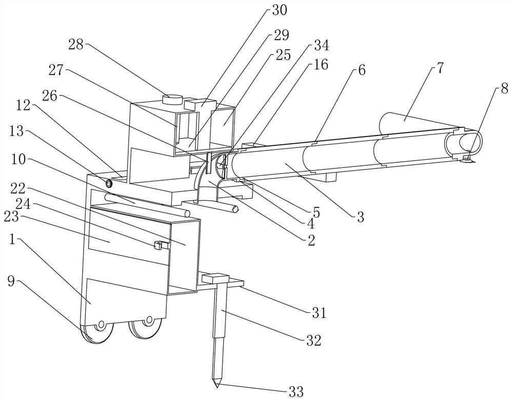
[0028] Embodiment 1. The present invention is an energy-saving irrigation device for water conservancy projects, which includes a support frame 1. The support frame 1 provides a fixed support foundation for subsequent structures, and the upper end of the support frame 1 is fixedly connected with a water elbow. 2. The lower end of the water elbow 2 is connected to the external water supply pump through a hose, the right end of the water elbow 2 is threaded with a connecting conduit 3, and the right end of the connecting conduit 3 is fixedly connected with a connecting thread ring 4 , the left end of the water elbow 2 is fixedly connected with the fastening threaded sleeve 5 matching the connecting threaded ring 4, through the cooperation of the connecting threaded ring 4 and the fastening threaded sleeve 5, the described The splicing of the water elbow 2 and the connecting conduit 3, the right end of the connecting conduit 3 is fixedly connected with the fastening threaded ring ...

Embodiment 2

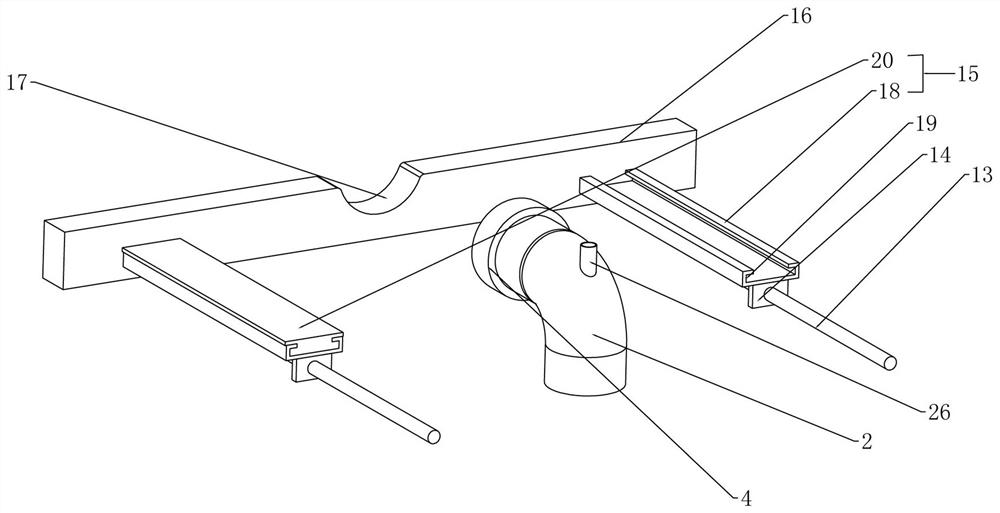
[0031] Embodiment 2. On the basis of Embodiment 1, when the connecting conduit 3 is spliced ​​and combined through threaded connection, the connecting conduit 3 will appear under the action of its own gravity and the gravity of water delivery during the water supply process. For the problem of tilting or breaking under force, this embodiment provides an auxiliary support structure for the connecting conduit 3. Specifically, the upper end of the support frame 1 is provided with two sliding rails 12 symmetrically distributed front and rear, so The sliding rails 12 are all rotatably connected with an adjusting lead screw 13, and the two adjusting lead screws 13 are connected by a transmission chain, so that the rotation of one of the adjusting lead screws 13 drives the other one of the adjusting lead screws 13 synchronously. Rotate, the described adjusting lead screw 13 is connected with the external driving device, the threaded sleeve 14 that is threadedly connected with the desc...

Embodiment 3

[0032]Embodiment 3, on the basis of Embodiment 2, when adjusting the position of the support horizontal plate 16 through the adjustment screw 13, the sliding distance of the threaded sleeve 14 is limited, so this embodiment provides A structure for further stretching the sliding telescopic plate 15, specifically, the sliding telescopic plate 15 includes a first-stage telescopic plate 18 fixedly connected to the upper end of the threaded sleeve 14, and the first-stage telescopic There is a T-shaped slide rail 19 in the plate 18, and a secondary telescopic plate 20 is slidingly connected to the left and right in the first-stage telescopic plate 18, and the lower end of the secondary telescopic plate 20 is fixedly connected with the T-shaped slide rail. 19 matched T-shaped slider 21, the right end of the secondary telescopic plate 20 is fixedly connected to the support horizontal plate 16, and through the cooperation of the T-shaped slider 21 and the T-shaped slide rail 19, the T...


PUM


Abstract

The invention provides an energy-saving irrigation device for a water conservancy project. The problems that an existing drip irrigation and sprinkling irrigation device needs to lay pipelines in a large area, cannot be moved anytime and anywhere, is complex to operate and cannot control irrigation time according to soil humidity conditions are solved. The device comprises a supporting frame, the upper end of the supporting frame is fixedly connected with a water bent pipe, the right end of the water bent pipe is in threaded connection with a connecting guide pipe, the right end of the connecting guide pipe is fixedly connected with a connecting threaded ring, and the left end of the water bent pipe is fixedly connected with a fastening threaded sleeve matched with the connecting threaded ring; the right end of the connecting guide pipe is fixedly connected with a fastening threaded ring matched with the fastening threaded sleeve, the right side of the connecting guide pipe at the left end is in threaded connection with a plurality of connecting guide pipes, the right end of the connecting guide pipe at the right end is in threaded connection with a water spraying pipe, and the lower end of the water spraying pipe is fixedly communicated with a plurality of nozzles. The device is simple in structure and has extremely high universality.

Description

technical field [0001] The invention relates to the technical field of water conservancy irrigation, in particular to an energy-saving irrigation device for water conservancy projects. Background technique [0002] Agricultural irrigation methods can generally be divided into traditional surface irrigation, ordinary sprinkler irrigation and micro-irrigation. Traditional surface irrigation includes border irrigation, furrow irrigation, flood irrigation and flood irrigation, but this kind of irrigation method often consumes a lot of water and has a low effective utilization rate of water, which is a very unreasonable agricultural irrigation method. [0003] In the environment of increasingly tense water resources, the use of sprinkler irrigation and drip irrigation is particularly important in agricultural production, which not only avoids the waste of water resources but also ensures that the land is not easy to harden. [0004] However, there are many problems in the curren...

Claims


Application Information

Patent Timeline
Patent Type & Authority Applications(China)
IPC IPC(8): A01G25/09A01G25/16A01G13/00A01M7/00B05B15/25
CPCA01G25/09A01G25/167A01G13/00A01M7/0042B05B15/25Y02A40/22
Inventor 郭宇李成威高春雷边传卿杨继安
Owner 河南基安建设集团有限公司
Why Eureka
Try Eureka