
Discharge chute bottom plate concrete truss track form drawing construction device

A construction device and a technology for a concrete truss, which is applied in the field of a truss track cantilevered bearing-loading formwork construction device, can solve the problems of inability to turn around, affect economic benefits, and high rail costs, and ensure concrete surface quality, beautiful appearance, and structural integrity. Good results

Inactive Publication Date: 2021-02-09
GEZHOUBA GRP NO 2 ENG
View PDF5 Cites 0 Cited by
  • Summary
  • Abstract
  • Description
  • Claims
  • Application Information

AI Technical Summary

Problems solved by technology

[0002] In the construction method of the spillway chute floor concrete in water conservancy and hydropower projects, in order to avoid the need to repair the pre-embedded cone holes on the surface of the concrete after the removal of the track erection, which will affect the structural integrity and appearance quality of the concrete, the main method is to use track embedding. In the construction method of drawing form, the track and supporting parts of this construction method are directly buried in the concrete of the bottom plate, which cannot be recycled, and the bottom plate of the chute is often long, so the amount of track is large, the cost of the track is high, and the waste of resources is serious, which affects economic benefits.

Method used


Image

  • Discharge chute bottom plate concrete truss track form drawing construction device
  • Discharge chute bottom plate concrete truss track form drawing construction device
  • Discharge chute bottom plate concrete truss track form drawing construction device

Examples


Embodiment Construction

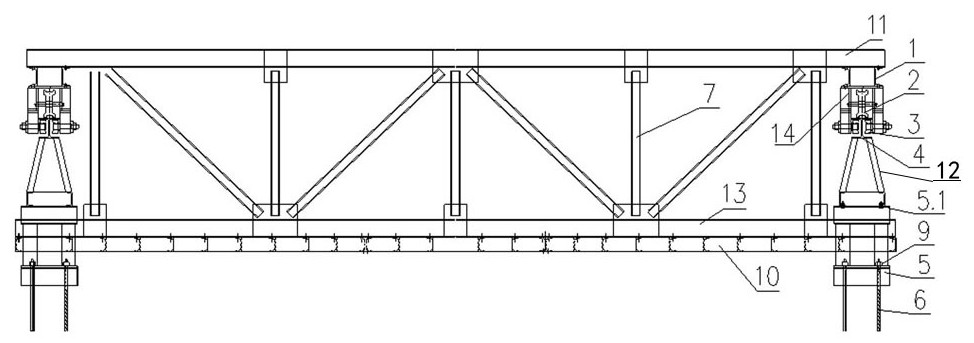
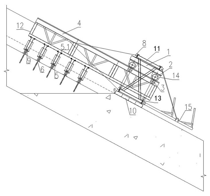
[0018] Track trusses 12 are installed along both sides of the chute, and its upper end is connected with the bottom surface of the track 4, and its lower end is connected with the track cushion 5. The track cushion 5 is connected and fixed with the solidified concrete through the anchor screw 6 and the nut 9, the two ends of the upper beam 11 of the die truss 7 are connected with the beam 1, the lower beam 13 is connected with the panel 10, and the lower end of the beam 1 is connected with the side plates 14 Connection, the walking wheel 2 on the side plate is located on the top of the track 4, the buckle wheel 3 on the side plate is located on the side of the track 4, the die truss 7 is suspended on the two tracks 4, and the track pedestal 5 ensures the back-to-back double The top surface of the upper flange plate of the channel steel connector 5.1 is at least 5 cm higher than the lower beam 13 of the die truss 7 . The lug plate 8 of the die truss 7 is connected with the trac...


PUM


Abstract

The invention relates to a discharge chute bottom plate concrete truss track form drawing construction device. The device solves the problems of large track consumption amount, high cost and serious resource waste of an existing device. Track trusses are arranged along two sides of a discharge chute, the upper ends thereof are connected with the bottom surfaces of tracks, and the lower ends thereof are connected with track pedestals; the track pedestals are fixedly connected with solidified concrete through anchoring screw rods and nuts, the two ends of an upper beam of a form drawing truss are connected with a cross beam, a lower beam of the form drawing truss is connected with a panel, the lower end of the cross beam is connected with two side plates, walking wheels on the side plates are located on the upper faces of the tracks, reverse buckling wheels on the side plates are located on the side faces of the tracks, and the form drawing truss is hung on the two tracks; and the trackpedestals ensure that the top surfaces of upper flange plates of back-to-back double-channel steel connecting pieces at the upper portions of the track pedestals are at least 5 cm higher than the lower beam of the form drawing truss, and lug plates of the drawing die truss are connected with the track trusses through steel wire ropes. According to the device, the track trusses, the track pedestalsand the like not only can be recycled, but also can be repeatedly used in multiple projects, so that the recycle utilization rate is high, and the economic benefit is high.

Description

technical field [0001] The invention belongs to the technical field of water conservancy and hydropower construction, and mainly relates to a construction device of a drawform construction device using a truss rail cantilever to support the concrete of a discharge trough bottom plate. Background technique [0002] In the construction method of the spillway chute floor concrete in water conservancy and hydropower projects, in order to avoid the need to repair the pre-embedded cone holes on the surface of the concrete after the removal of the track erection, which will affect the structural integrity and appearance quality of the concrete, the main method is to use track embedding. In the construction method of drawing form, the track and supporting parts of this construction method are directly buried in the concrete of the bottom plate, which cannot be recycled, and the bottom plate of the chute is often long, so the amount of track is large, the cost of the track is high, an...

Claims


Application Information

Patent Timeline
IPC IPC(8): E02B8/06E02D15/02
CPCE02B8/06E02D15/02E02D2250/0007
Inventor 曾良红程华倩饶昌福刘红岩周振兴刘超孙金鹏
Owner GEZHOUBA GRP NO 2 ENG
Features
  • Generate Ideas
  • Intellectual Property
  • Life Sciences
  • Materials
  • Tech Scout
  • Unparalleled Data Quality
  • Higher Quality Content
  • 60% Fewer Hallucinations
Learn More