
Intelligent vehicle path planning method for improving artificial potential field algorithm

An artificial potential field and path planning technology, applied in vehicle position/route/height control, navigation calculation tools, two-dimensional position/channel control, etc., can solve the problem of difficult balance between trajectory smoothness and moving steps, calculation It is impossible to adjust the step size and trajectory of moving out of the affected area to achieve the effect of reducing redundant distance

Active Publication Date: 2021-02-09
ANHUI UNIVERSITY OF TECHNOLOGY AND SCIENCE
View PDF6 Cites 16 Cited by
  • Summary
  • Abstract
  • Description
  • Claims
  • Application Information

AI Technical Summary

Problems solved by technology

[0005] The purpose of the present invention is to provide a smart car path planning method that improves the artificial potential field algorithm, so as to solve the problem that the prior art cannot automatically adjust the step size and track of moving out of the affected area according to the size of the affected area of ​​the local minimum point, and the smoothness of the track. Technical issues that are difficult to balance with the number of moving steps and the amount of calculation

Method used


Image

  • Intelligent vehicle path planning method for improving artificial potential field algorithm
  • Intelligent vehicle path planning method for improving artificial potential field algorithm
  • Intelligent vehicle path planning method for improving artificial potential field algorithm

Examples


Embodiment Construction

[0044] The specific embodiments of the present invention will be described in further detail below by describing the embodiments with reference to the accompanying drawings, so as to help those skilled in the art have a more complete, accurate and in-depth understanding of the inventive concepts and technical solutions of the present invention.

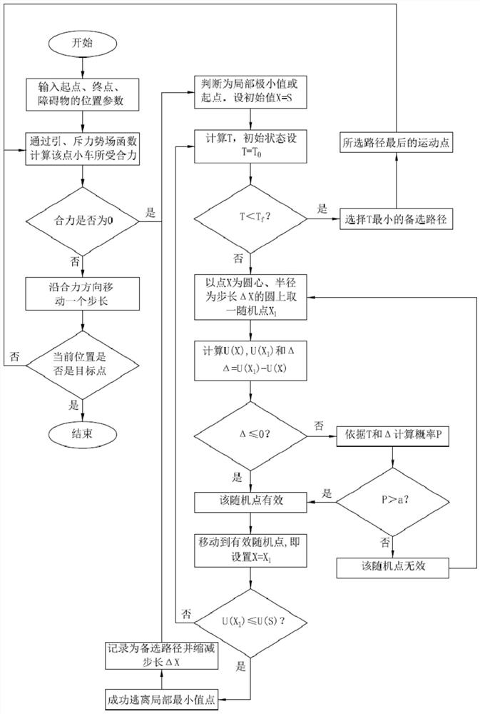
[0045] Such as figure 1 As shown, the present invention provides a smart car path planning method that improves the artificial potential field algorithm, including the following steps.

[0046] Step 1. Collect the starting point, target point, and obstacle position parameters, and set the starting point, end point, and obstacle point in the planned path.

[0047] Step 2. Construct the gravitational potential field function and the repulsive force potential field function according to the positions of the smart car, the target point, and the obstacle point respectively.

[0048] Among them, the gravitational potential field function U c...


PUM


Abstract

The invention discloses an intelligent vehicle path planning method based on an improved artificial potential field algorithm, and the method comprises the steps: collecting the position parameters ofa starting point, a target point and an obstacle, constructing a gravitational potential field function and a repulsion potential field function, and obtaining the resultant force of an intelligent vehicle at a current position point through calculation according to the gravitational potential field function and the repulsion potential field function; dragging the intelligent vehicle to advance towards the target point according to the resultant force to generate a corresponding path; and a step of escaping from the local minimum point: taking a random point from a circle taking the current point or the obtained motion point as the center of the circle and the radius as the step length, judging whether the random point is set as the next motion point or not by utilizing the constructed probability function, judging whether the random point escapes from the local minimum point or not according to the size of the potential field, and finally limiting the number of iterations, namely thestep number through a potential energy threshold; and finally, selecting an escape track with the best smoothness in the limited step number. The step length and the track of moving out of the influence area are automatically adjusted according to the size of the local minimum value point influence area, the track smoothness, the moving step number and the calculated amount are difficult to balance, and the problems in the prior art are solved.

Description

technical field [0001] The invention belongs to the technical field of artificial intelligence and relates to an intelligent vehicle path planning method for improving an artificial potential field algorithm. Background technique [0002] The path planning method is to plan a collision-free path from the initial state (position, attitude) to the target state according to certain evaluation criteria in the obstacle environment, mainly considering the geometric relationship between the local moving subject and the obstacle, and finding A path without collisions. A path is a static geometric trajectory that does not contain the concept of time, and usually represents the position and attitude relationship of an intelligent vehicle in Cartesian coordinates. [0003] Because the artificial potential field method is simple and practical, has good real-time performance, simple structure, and is convenient for real-time control of the bottom layer, it has been widely used in real-t...

Claims


Application Information

Patent Timeline
Patent Type & Authority Applications(China)
IPC IPC(8): G01C21/20G05D1/02
CPCG01C21/20G05D1/0088G05D1/0212
Inventor 时培成倪璇高立新梁涛年王金桥陈现敏马康潘之杰肖平张荣芸杨胜兵刘糠继齐恒马永富
Owner ANHUI UNIVERSITY OF TECHNOLOGY AND SCIENCE
Learn More