Gas detection device and gas detection method

A technology for gas detection and detection mechanism, which can be used in measurement devices, instruments, material analysis by electromagnetic means, etc., and can solve problems such as threshold drop.

Pending Publication Date: 2021-02-09
FIGARO ENG INC
View PDF1 Cites 0 Cited by
  • Summary
  • Abstract
  • Description
  • Claims
  • Application Information

AI Technical Summary

Problems solved by technology

Therefore, in JP6274649B, if the resistance value in the air increas

Method used


Image

  • Gas detection device and gas detection method
  • Gas detection device and gas detection method
  • Gas detection device and gas detection method

Examples


Embodiment

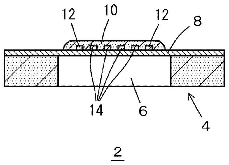
[0027] exist Figure 1 to Figure 9 The gas detection device and the gas detection method of the embodiment are shown in . figure 1 An example of the MEMS gas sensor 2 is shown, 4 is a substrate such as silicon, 6 is a cavity, and 8 is an insulating film, which may be either a diaphragm or a bridge. A thick metal oxide semiconductor 10 is provided on the insulating film 8 , the metal oxide semiconductor 10 is heated by a heater 12 , and the resistance value of the metal oxide semiconductor 10 is taken out by an electrode 14 . In addition, the electrode 14 may not be provided, and the parallel resistance of the heater 12 and the metal oxide semiconductor 10 may be output. The metal oxide semiconductor 10 is, for example, SnO 2 , but can also be WO 3 、In 2 o 3 etc., the kind is arbitrary. In addition to the above, the MEMS gas sensor 2 is provided with a case, a filter such as activated carbon, and the like.

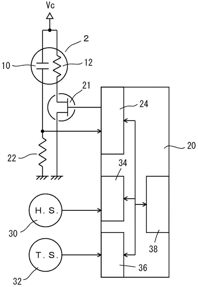
[0028] figure 2 The structure of the gas detection device is...


PUM


Abstract

The present invention uses a MEMS gas sensor which has a metal oxide semiconductor and a heater provided on an insulating film disposed in a cavity of a substrate. The heater is operated at a prescribed operating cycle and with a prescribed pulse width by a drive circuit so as to heat the metal oxide semiconductor. When a humidity detection means detects that the atmosphere has high humidity, thedrive circuit either stops the operation of the heater or extends the cycle.

Description

technical field [0001] The invention relates to a gas detection device and a gas detection method. Background technique [0002] It is known that a MEMS (Micro Electro Mechanical System) gas sensor using a metal oxide semiconductor is easily affected by humidity (Patent Document 1: JP6274649B). In the MEMS gas sensor, a metal oxide semiconductor is heated for a predetermined period of time, for example, at a predetermined cycle, and gas is detected from the resistance value of the metal oxide semiconductor during heating. In the initial stage of heating, the resistance value of the metal oxide semiconductor drops rapidly. Also, in JP6274649B, since the resistance value drops slowly in high humidity and quickly in medium-low humidity, the rapid drop is detected based on the signal of the gas sensor. [0003] If exposed to high humidity for a long period of time, the resistance value of the metal oxide semiconductor in the air and the resistance value in the gas both increas...

Claims


Application Information

Patent Timeline
IPC IPC(8): G01N27/12
CPCG01N27/128G01N27/121G01N27/123
Inventor 佐井正和井泽邦之河口智博
Owner FIGARO ENG INC
Why Eureka
Try Eureka