
Steel bar cutting device for constructional engineering

A cutting device and technology of construction engineering, applied in the field of construction engineering, can solve the problems of heavy steel bar, low cutting efficiency, messy steel bar cutting, etc., and achieve the effects of high degree of automation, fast adjustment speed, and improved stability

Inactive Publication Date: 2021-02-12
梁少龙
View PDF9 Cites 0 Cited by
  • Summary
  • Abstract
  • Description
  • Claims
  • Application Information

AI Technical Summary

Problems solved by technology

Among them, "housing construction" refers to projects that have roofs, beams, walls, foundations, and can form internal spaces to meet the needs of people's production, living, learning, and public activities. In the construction process of construction projects, steel bars are the most commonly used building materials One, cutting is often required during the use of steel bars, but the existing steel bar cutting equipment is manually loaded, the weight of the steel bar is heavy, time-consuming and laborious, and it is impossible to quickly cut out the same length of steel bar according to the construction needs. Moreover, the switching of the cutting length of the steel bar is complicated, the cutting efficiency is low, and the cutting of the steel bar after cutting is messy, and the post-processing is time-consuming and laborious. Therefore, we propose a steel bar cutting device for construction engineering

Method used


Image

  • Steel bar cutting device for constructional engineering
  • Steel bar cutting device for constructional engineering
  • Steel bar cutting device for constructional engineering

Examples


Embodiment Construction

[0031] In order to make the technical means, creative features, goals and effects achieved by the present invention easy to understand, the present invention will be further described below in conjunction with specific embodiments.

[0032] In the description of the present invention, it should be noted that the terms "upper", "lower", "inner", "outer", "front end", "rear end", "both ends", "one end", "another end" The orientation or positional relationship indicated by etc. is based on the orientation or positional relationship shown in the drawings, and is only for the convenience of describing the present invention and simplifying the description, rather than indicating or implying that the referred device or element must have a specific orientation, use a specific Azimuth configuration and operation, therefore, should not be construed as limiting the invention. In addition, the terms "first" and "second" are used for descriptive purposes only, and should not be understood ...


PUM


Abstract

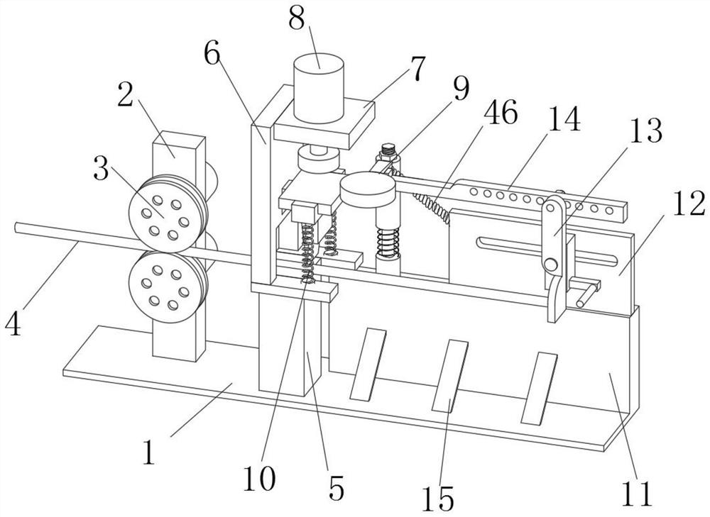
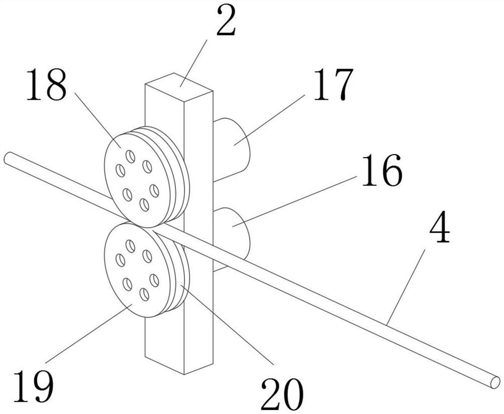
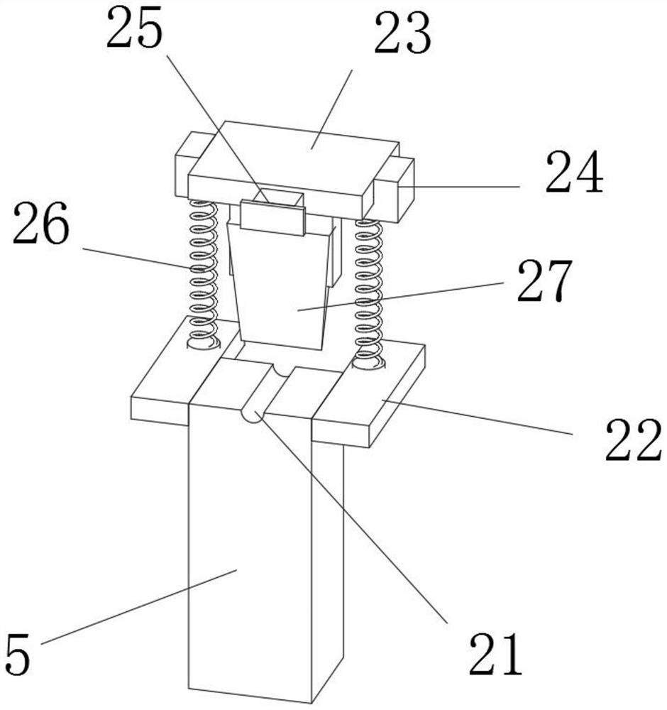
The invention discloses a steel bar cutting device for constructional engineering. The steel bar cutting device comprises a bottom plate. A supporting column is fixedly installed on the left portion of the upper end of the bottom plate, a conveying device is arranged on the supporting column, a supporting base is fixedly installed at the upper end of the bottom plate, the upper portion of the front end and the upper portion of the rear end of the supporting base are jointly and fixedly connected with a cutting device, a supporting plate is arranged on the left portion of the cutting device, aconnecting transverse plate is fixedly connected to the upper portion of the right end of the supporting plate, a pressing device is arranged on the connecting transverse plate, a rear supporting plate is fixedly installed on the rear side of the right portion of the upper end of the bottom plate, an extrusion device is fixedly installed on the left portion of the upper end of the rear supportingplate, a sliding connecting plate is fixedly installed on the right portion of the upper end of the rear supporting plate, a third spring is fixedly connected between the sliding connecting plate andthe extrusion device, and a pushing device is connected to the middle of the sliding connecting plate in a penetrating mode. According to the steel bar cutting device for constructional engineering, steel bars of different length specifications can be cut out, the cutting efficiency is high, and the automation degree is high.

Description

technical field [0001] The invention relates to the technical field of construction engineering, in particular to a steel bar cutting device for construction engineering. Background technique [0002] Construction engineering refers to the engineering entity formed through the construction of various housing buildings and their ancillary facilities and the installation activities of supporting lines, pipelines and equipment. Among them, "housing construction" refers to projects that have roofs, beams, walls, foundations, and can form internal spaces to meet the needs of people's production, living, learning, and public activities. In the construction process of construction projects, steel bars are the most commonly used building materials One, cutting is often required during the use of steel bars, but the existing steel bar cutting equipment is manually loaded, the weight of the steel bar is heavy, time-consuming and laborious, and it is impossible to quickly cut out the s...

Claims


Application Information

Patent Timeline
IPC IPC(8): B21F11/00B21F23/00
CPCB21F11/00B21F23/00
Inventor 梁少龙
Owner 梁少龙
Learn More