
Special-shaped tooth groove small tooth type bimetal saw blade

A special-shaped tooth and bimetal technology, which is applied in the field of bimetal saw blades, can solve the problems of easy springback of the divided teeth and reduce the stress concentration of the tooth groove, so as to achieve low tolerance of the difference of the divided teeth, reduce the stress concentration of the tooth groove, The effect of avoiding tooth pulling phenomenon

Pending Publication Date: 2021-02-12
浙江思普锯业有限公司
View PDF0 Cites 1 Cited by
  • Summary
  • Abstract
  • Description
  • Claims
  • Application Information

AI Technical Summary

Problems solved by technology

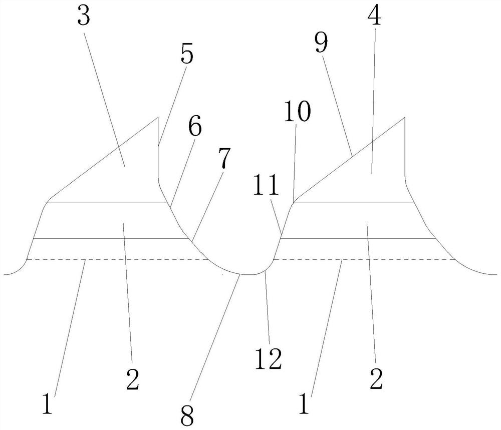
[0008] This special-shaped bimetal saw blade with small tooth groove is aimed at bimetal saw blades with small tooth pitch products in the range of 8tpi to 18tpi. Through reasonable tooth groove shape design, the tooth groove can be deepened and the same stress distribution characteristics of the tooth groove can be maintained, and even the teeth can be reduced. Groove stress concentration; at the same time, the depth of the tooth groove is increased to ensure that the weld between adjacent teeth is milled through, preventing the weld from not penetrating and causing the weld to be too long, resulting in excessive stress and weakening the strength of the weld and cutting Tooth tip pulling phenomenon; also ensure that the part of the tooth is above the bottom of the tooth groove, to avoid the back of the spring steel belt being twisted below the tooth groove, which will affect the fatigue life of the band saw, and the part of the tooth is easy to rebound, resulting in a rapid saw cut reduction and other issues

Method used


Image

  • Special-shaped tooth groove small tooth type bimetal saw blade
  • Special-shaped tooth groove small tooth type bimetal saw blade

Examples


Embodiment Construction

[0023] The following are specific embodiments of the present invention and in conjunction with the accompanying drawings, the technical solutions of the present invention are further described, but the present invention is not limited to these embodiments.

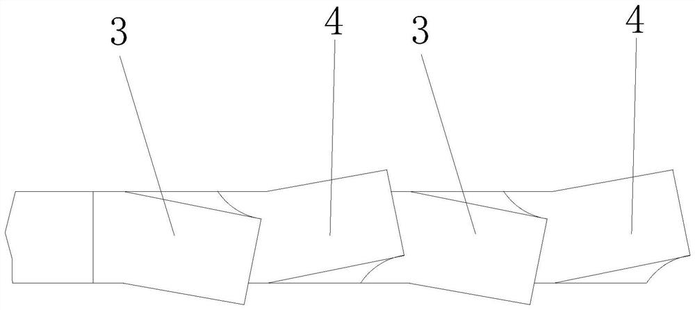
[0024] Such as Figure 1 to Figure 2 As shown, the bimetal saw blade with special-shaped tooth groove and small teeth includes a saw blade band, and a number of teeth in a continuous arrangement are fixed on one edge of the saw blade band through a weld 2, and the teeth are all inclined in the same direction to form a straight line Extended sawing edge, one side of the teeth is the rake face, the other side is the flank face, a tooth groove 8 is set between adjacent teeth, the tooth groove 8 is located below the weld 2, and the rake face is The vertical blade 5, the vertical blade 5 is located above the weld 2, the flank is a slanted blade 9, the slanted blade 9 is located above the weld 2, and the vertical blade 5 and the...


PUM


Abstract

The invention provides a special-shaped tooth groove small tooth type bimetal saw blade which comprises multiple teeth on a saw blade band, the multiple teeth deflect towards the same direction to form saw cutting edges extending linearly, one side of each tooth is a front cutter face, the other side of each tooth is a rear cutter face, a tooth groove is formed between every two adjacent teeth, and the tooth grooves are located below a weld joint. The front cutter faces are vertical cutter edges, the vertical cutting edges are located above the weld joint, the rear cutter faces are oblique line cutting edges, the oblique line cutting edges are located above the weld joint, the vertical cutting edges and the tooth grooves are connected through at least two straight line sections and / or arcline sections, first front line sections connected with the vertical cutting edges deflect forwards to expand the front end of the weld line, and second front line sections connected with the first front line sections deflect forwards to be in transition connection with the tooth grooves. The oblique line cutting edges are connected with the tooth grooves through at least three straight line sections and / or arc sections, first rear line sections connected with the oblique line cutting edges are bent downwards, second rear line sections connected with the first rear line sections deflect backwards to extend the rear end of the weld line, and third rear line sections connected with the second rear line sections are bent backwards to be in transition connection with the tooth grooves.

Description

technical field [0001] The invention belongs to the technical field of tools, and relates to a tooth structure of a saw blade, in particular to a bimetallic saw blade with special-shaped grooves and small teeth. Background technique [0002] The saw blade is a steel sheet with a toothed edge, and the toothed edge is the main part of the saw blade. The bimetal saw blade is a saw blade welded by two metals, specifically, it is composed of a spring steel saw body and a high-speed steel saw tooth. For cutting pipe fittings, solid bodies, wood, plastics and all machinable metals. Compared with single metal saw blades, it has higher heat and wear resistance and longer life. Strong flexibility, which can effectively avoid breakage and damage during cutting. [0003] The production process of bimetallic saw blades includes several key processes such as bimetallic steel strip production-milling-tooth division-quenching-tempering; the spring steel of the saw blade band can withstan...

Claims


Application Information

Patent Timeline
Patent Type & Authority Applications(China)
IPC IPC(8): B23D61/12
CPCB23D61/12
Inventor 卢俊辰
Owner 浙江思普锯业有限公司
Learn More