
Double-sided groove milling and drilling device for rudder decorating part

A technology for drilling devices and decorative parts, which is applied in the direction of milling machine equipment, milling machine equipment details, other manufacturing equipment/tools, etc., can solve the problems of inconvenient processing, achieve high processing efficiency and facilitate streamlined processing

Inactive Publication Date: 2021-02-12
深圳市华博自动化设计有限公司
View PDF0 Cites 2 Cited by
  • Summary
  • Abstract
  • Description
  • Claims
  • Application Information

AI Technical Summary

Problems solved by technology

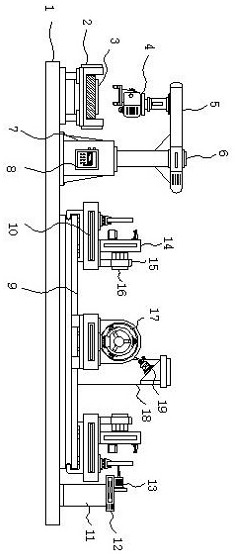
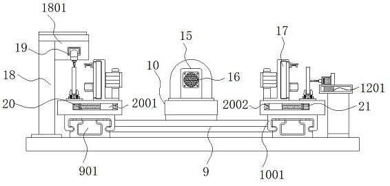
[0003] During the production of the rudder decoration, the main ring usually needs to be drilled to facilitate the assembly of the rudder stock, and both sides of the main ring need to be grooved to make the overall structure more beautiful. The traditional processing device grooves on the opposite side After processing, it needs to be manually removed and turned over and clamped again, which is inconvenient for processing

Method used


Image

  • Double-sided groove milling and drilling device for rudder decorating part
  • Double-sided groove milling and drilling device for rudder decorating part
  • Double-sided groove milling and drilling device for rudder decorating part

Examples


Embodiment Construction

[0027] The following will clearly and completely describe the technical solutions in the embodiments of the present invention with reference to the accompanying drawings in the embodiments of the present invention. Obviously, the described embodiments are only some, not all, embodiments of the present invention.

[0028] In the description of the present invention, unless otherwise stated, the meaning of "plurality" is two or more; the terms "upper", "lower", "left", "right", "inner", "outer" , "front end", "rear end", "head", "tail", etc. indicate the orientation or positional relationship based on the orientation or positional relationship shown in the drawings, and are only for the convenience of describing the present invention and simplifying the description, rather than Indicates or implies that the device or element referred to must have a particular orientation, be constructed and operate in a particular orientation, and therefore should not be construed as limiting the...


PUM


Abstract

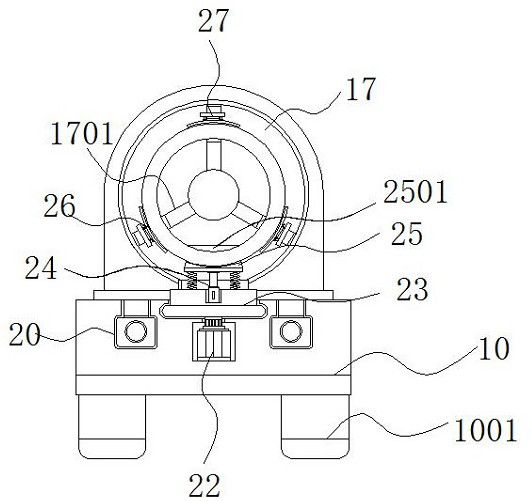
The invention discloses a double-face groove milling and drilling device for a rudder decorating part. The device comprises a bottom plate, a feeding mechanism, a machining table, a rotary disc and alimiting base, wherein a conveying belt is fixed to one side of the top of the bottom plate, main rings are evenly arranged on the conveying belt, and fixing bases are arranged on the other side of the top of the bottom plate and one end of the top of the bottom plate, and the tops of the fixed bases are provided with an electromagnetic slide rail. According to the double-sided groove milling anddrilling device for the rudder decorating part, the rotating disc is arranged, the limiting seat is arranged above the rotating disc through a spring, and the bottoms of the main rings are embedded into a limiting groove of the limiting seat in the feeding process, so that primary limiting on the main rings is facilitated, and after groove milling on one sides of the main rings is completed, clamping plates loosen the main rings; and the rotating disc can drive the main ring to rotate by 180 degrees under the action of a gear motor, the unmachined facse of the main rings face outwards, and then the clamping plates clamp the main rings again, so that groove milling machining can be conducted on the other faces of the main rings, manual turn-over is not needed, and machining is more convenient.

Description

technical field [0001] The invention relates to the technical field of automatic processing of decorative pendants, in particular to a double-sided milling and drilling device for rudder decorative parts. Background technique [0002] Ornaments are items used for decoration. The general purpose is to beautify the personal appearance, decorate the living room, beautify the public environment, and decorate the car. Therefore, the decorative ornaments can be divided into the following categories: home accessories, clothing accessories, car accessories, etc. There is a boat A rudder trim, the main body of which is a rudder-like metal consisting of a main ring, a center piece and a rudder stock. [0003] During the production of the rudder decoration, the main ring usually needs to be drilled to facilitate the assembly of the rudder stock, and both sides of the main ring need to be grooved to make the overall structure more beautiful. The traditional processing device grooves on ...

Claims


Application Information

Patent Timeline
Patent Type & Authority Applications(China)
IPC IPC(8): B23P23/02B23C3/28B23K26/382B23K26/70
CPCB23C3/28B23P23/02B23K26/382B23K26/702
Inventor 陈静邝润森
Owner 深圳市华博自动化设计有限公司
Learn More