Hardware inner wall grinding equipment

A technology for hardware and equipment, which is applied in the field of grinding equipment for the inner wall of hardware, can solve the problems of complex operation and cleaning of debris generated during grinding, and achieve the effect of precise and fast grinding

Pending Publication Date: 2021-02-12
杨庆金
View PDF4 Cites 6 Cited by
  • Summary
  • Abstract
  • Description
  • Claims
  • Application Information

AI Technical Summary

Problems solved by technology

[0005] In order to overcome the shortcomings of the prior art that the operation is complicated and the debris generated during grinding cannot be cleaned, the technical problem of the present invention is: to provide a hardware that can clean up the debris generated during the grinding of the inner wall of the hardware and is convenient for people to collect. Parts inner wall grinding equipment

Method used


Image

  • Hardware inner wall grinding equipment
  • Hardware inner wall grinding equipment
  • Hardware inner wall grinding equipment

Examples


Embodiment 1

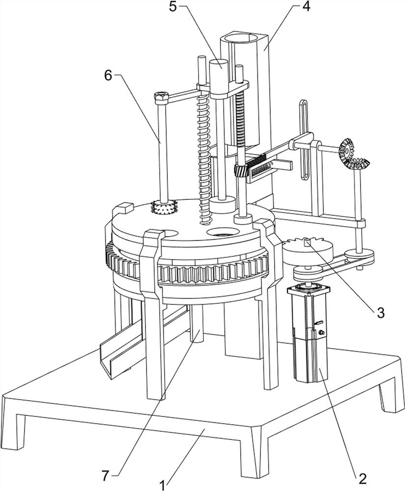
[0023] A hardware inner wall grinding equipment, such as Figure 1-3 As shown, it includes a base 1, a servo motor 2, a first rotating shaft 3, a feeding mechanism 4 and a grinding mechanism 5, a servo motor 2 is provided on the right front side of the top of the base 1, and a first rotating shaft 3 is provided on the output shaft of the servo motor 2. The top of the base 1 is provided with a feeding mechanism 4 , and the top of the base 1 is provided with a grinding mechanism 5 .

[0024] When people need to polish the inner wall of the hardware, first people place the hardware in the feeding mechanism 4, and then the servo motor 2 can be started, the output shaft of the servo motor 2 drives the first rotating shaft 3 to rotate, and the first rotating shaft 3 drives the feeding mechanism 4. The feeding mechanism 4 operates, the feeding mechanism 4 operates and then pushes the hardware into the grinding mechanism 5, and then the first rotating shaft 3 drives the grinding mecha...

Embodiment 2

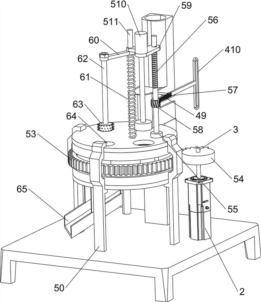
[0030] On the basis of Example 1, such as figure 1 , image 3 and Figure 4 Shown, also comprise cleaning mechanism 6, and cleaning mechanism 6 comprises slide block 60, second spring 61, connecting rod 62, brush 63 and unloading plate 65, slide bar 511 slide type is provided with slide block 60, slide block 60 The second spring 61 is connected with the upper support plate 51, the second spring 61 is sleeved on the slide bar 511, the left side of the slide block 60 is provided with a connecting rod 62, the bottom of the connecting bar 62 is provided with a brush 63, and the left side of the upper support plate 51 There is a feed hole 64 on the side, and a discharge plate 65 is provided at the bottom of the lower support plate 52, and the discharge plate 65 is located below the discharge hole.

[0031] When the nut block 59 moves downward, the nut block 59 drives the slide block 60 to slide downward, the second spring 61 is compressed, and the slide block 60 drives the connec...


PUM


Abstract

The invention relates to grinding equipment, in particular to hardware inner wall grinding equipment. According to the hardware inner wall grinding equipment, chippings generated during hardware innerwall grinding can be cleared away, and people can collect the chippings conveniently. The hardware inner wall grinding equipment comprises a base, a first rotating shaft, a feeding mechanism and a grinding mechanism, wherein a servo motor is arranged on the base; the first rotating shaft is arranged on an output shaft of the servo motor; the feeding mechanism is arranged at the top of the base; and the grinding mechanism is arranged at the top of the base. The servo motor is started to achieve rotation of the first rotating shaft, then under cooperation of the feeding mechanism and the grinding mechanism, rapid grinding of hardware is achieved, and intermittent discharging of the hardware can be achieved through the feeding mechanism.

Description

technical field [0001] The invention relates to a grinding device, in particular to a grinding device for inner walls of hardware parts. Background technique [0002] Hardware refers to tools obtained by processing and casting gold, silver, copper, iron, tin and other metals, which are used to fix things, process things, decorate, etc. [0003] For the different uses of hardware, people will make hardware into various shapes, the more common one is tubular, and tubular hardware often needs to be cut or welded in the production process, so that it will be in the cutting or welding. Burrs are produced, which is not conducive to the use of hardware. The existing grinding devices are generally large in size and complicated to operate, and cannot clean up the debris generated during grinding. As a result, after the inner wall of the hardware is polished, manual cleaning is required. [0004] Therefore, there is an urgent need to develop a hardware inner wall grinding device capa...

Claims


Application Information

Patent Timeline
Patent Type & Authority Applications(China)
IPC IPC(8): B24B5/40B24B5/35B08B9/043
CPCB24B5/40B24B5/355B24B5/35B08B9/0436
Inventor 杨庆金
Owner 杨庆金
Why Eureka
Try Eureka