Automatic polishing equipment for iron pot cover inner surface for workshop production
An automatic polishing and inner surface technology, applied in grinding/polishing equipment, surface polishing machine tools, metal processing equipment, etc., can solve the problems of troublesome operation, time-consuming and labor-intensive efficiency, and achieve the effect of simple and convenient operation and improved work efficiency.
- Summary
- Abstract
- Description
- Claims
- Application Information
AI Technical Summary
Problems solved by technology
Method used
Image
Examples
Embodiment 1
[0067] An automatic polishing equipment for the inner surface of an iron pot cover for workshop production, such as figure 1 As shown, it includes a base 1, a frame 2, a rotating mechanism 3 and a manual pressing mechanism 4, the base 1 is provided with a frame 2, the base 1 is provided with a rotating mechanism 3, the rotating mechanism 3 is connected with the frame 2, and the base 1 is provided with a manual pressing mechanism 4, and the manual pressing mechanism 4 cooperates with the rotating mechanism 3.
[0068] Manual polishing operation is cumbersome, time-consuming and labor-intensive, and the efficiency is low. This equipment can realize automatic polishing, which is easy to operate, saves time and effort, and has high efficiency. The mechanism 3 runs and drives the pot cover to rotate, and then people make the manual pressing mechanism 4 operate, and the manual pressing mechanism 4 cooperates with the rotating mechanism 3 to polish the pot cover. After the pot cover ...
Embodiment 2
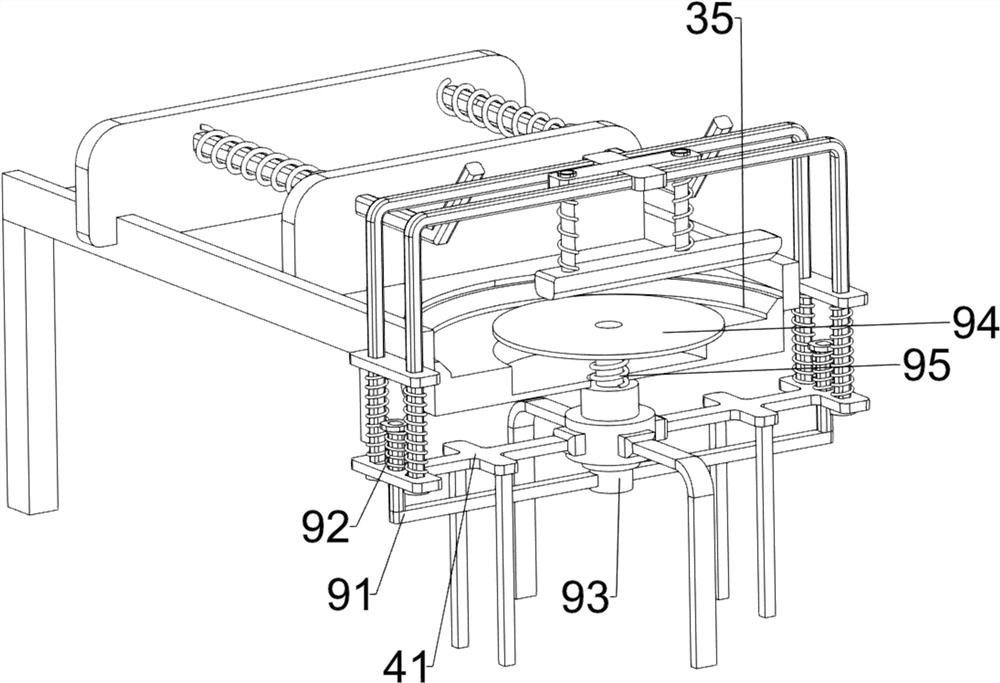
[0070] On the basis of Example 1, such as figure 2 , image 3 and Figure 7 As shown, the rotating mechanism 3 includes a first connecting rod 31, a motor 32, a fixed through shaft 33, a rotating through shaft 34, a rotating disk 35 and a belt 36, and the front and rear sides of the left part of the bottom side of the frame 2 are provided with first connecting rods. Connecting rod 31, motor 32 is installed on the inner side of the first connecting rod 31 bottom, base 1 top inner side is connected with fixed through shaft 33, fixed through shaft 33 is connected with manual pressing down mechanism 4, and fixed through shaft 33 internal rotation type is provided with rotating through shaft. Shaft 34, the top of the rotating shaft 34 is provided with a rotating disc 35, the rotating disc 35 is rotatably connected with the frame 2, the rotating disc 35 cooperates with the manual pressing mechanism 4, and the top of the rotating shaft 34 is connected with the output shaft of the m...
Embodiment 3
[0075] On the basis of Example 2, such as figure 1 , Figure 4 , Figure 5 , Image 6 and Figure 7 As shown, it also includes anti-skid rubber blocks 5, and the top of the rotating disc 35 is provided with four anti-skid rubber blocks 5.
[0076] People put the pot cover on the rotating disk 35, and the non-slip rubber block 5 contacts with the bottom of the pot cover. 5. Move, the anti-slip rubber block 5 can prevent the pot cover from moving at will. If the device is used again, just repeat the above steps.
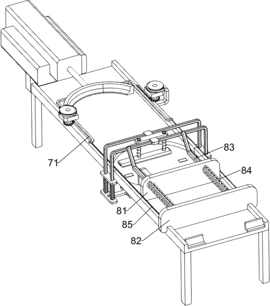
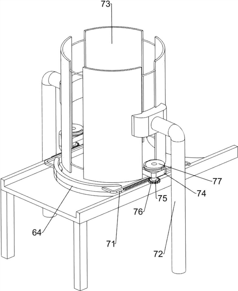
[0077] Also includes a pusher mechanism 6, the base 1 is provided with a pusher mechanism 6, the pusher mechanism 6 cooperates with the frame 2, the pusher mechanism 6 includes a third connecting rod 61, a mounting groove 62, a cylinder 63 and a crescent push plate 64, the upper right side of the base 1 is provided with an installation groove 62, a third connecting rod 61 is connected between the left side of the bottom of the installation groove 62 and the right ...
PUM
 Abstract
Description
Claims
Application Information
 - R&D Engineer
- R&D Manager
- IP Professional
- Industry Leading Data Capabilities
- Powerful AI technology
- Patent DNA Extraction
Browse by: Latest US Patents, China's latest patents, Technical Efficacy Thesaurus, Application Domain, Technology Topic, Popular Technical Reports.
© 2024 PatSnap. All rights reserved.Legal|Privacy policy|Modern Slavery Act Transparency Statement|Sitemap|About US| Contact US: help@patsnap.com


