Supercharge Your Innovation With Domain-Expert AI Agents!

Magnetic gripper

A gripper and magnetic technology, applied in the field of magnetic grippers, can solve the problems of easy damage of grippers, no buffer mechanism for magnetic grippers, and no stabilizing device for magnetic grippers, so as to improve safety performance, move stably, and prevent mechanism damage Effect

Inactive Publication Date: 2021-02-12
陆水龙
View PDF4 Cites 2 Cited by
  • Summary
  • Abstract
  • Description
  • Claims
  • Application Information

AI Technical Summary

Problems solved by technology

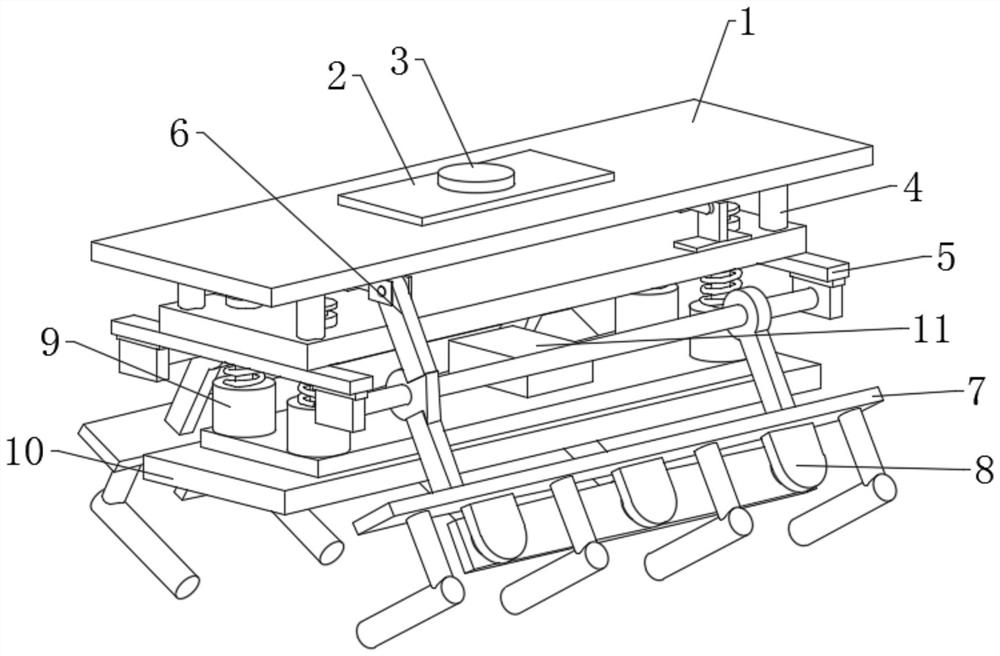
The movement mechanism enables the hand to complete various rotations, movements or compound movements to achieve prescribed actions and change the position and posture of the grasped object. The magnetic gripper is used to grab steel parts. 1. The existing magnetic gripper There is no stabilizing device for the claws in the process of grabbing steel parts, so that the magnetic grippers are not stable enough to grab steel parts. 2. The existing magnetic grippers do not have a buffer mechanism, so that the grippers are easily damaged when grabbing steel parts. Therefore, we propose a magnetic gripper

Method used


Image

  • Magnetic gripper
  • Magnetic gripper
  • Magnetic gripper

Examples


Embodiment Construction

[0023] In order to make the technical means, creative features, goals and effects achieved by the present invention easy to understand, the present invention will be further described below in conjunction with specific embodiments.

[0024] In the description of the present invention, it should be noted that the terms "upper", "lower", "inner", "outer", "front end", "rear end", "both ends", "one end", "another end" The orientation or positional relationship indicated by etc. is based on the orientation or positional relationship shown in the drawings, and is only for the convenience of describing the present invention and simplifying the description, rather than indicating or implying that the referred device or element must have a specific orientation, use a specific Azimuth configuration and operation, therefore, should not be construed as limiting the invention. In addition, the terms "first" and "second" are used for descriptive purposes only, and should not be understood ...


PUM


Abstract

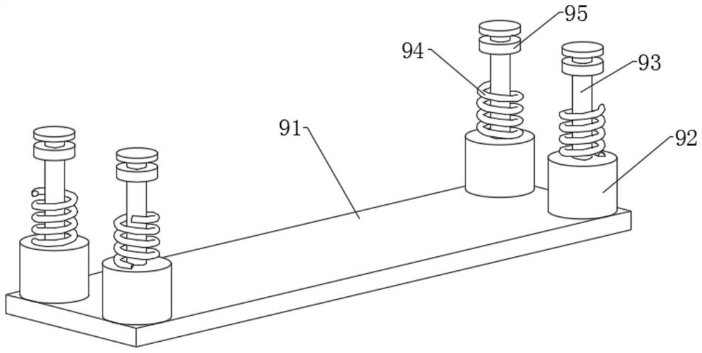
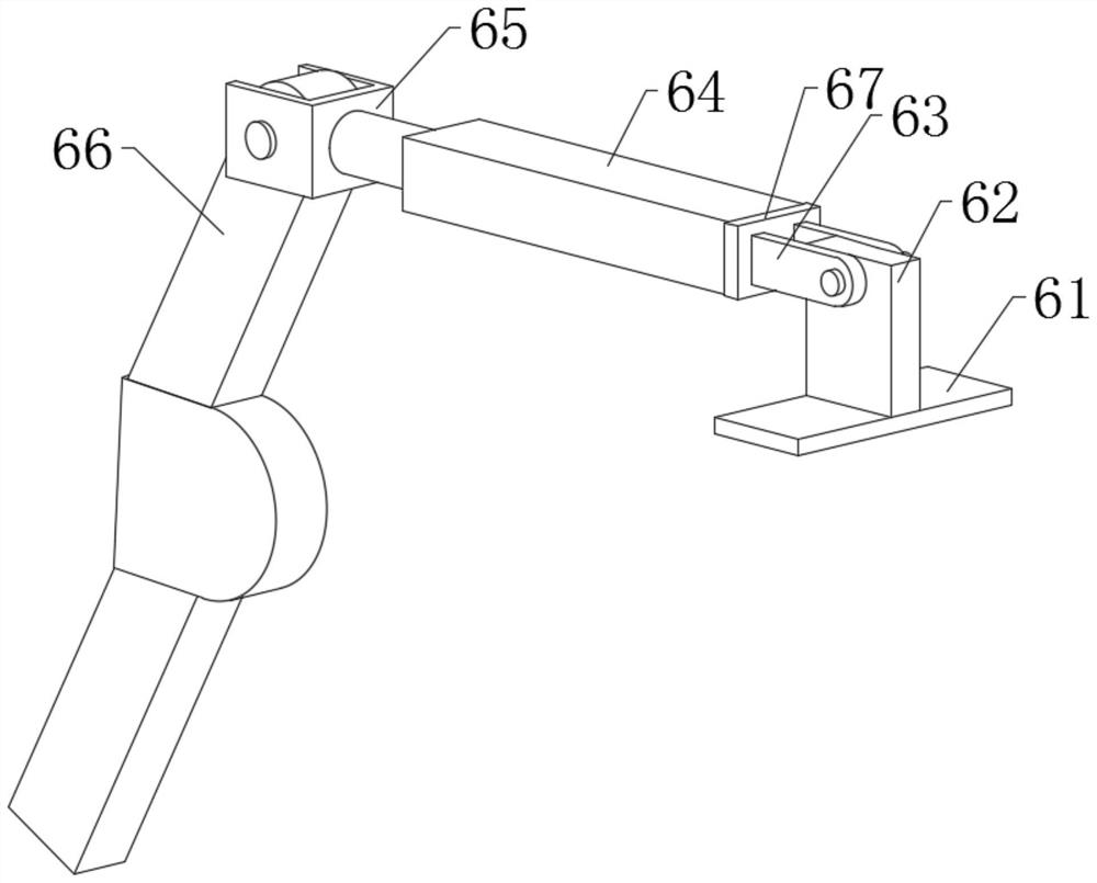
The invention discloses a magnetic gripper. The magnetic gripper comprises a driving plate, wherein a base plate is fixedly connected to the middle of the upper end of the driving plate, four sets ofsupporting rods are fixedly connected to the lower end of the driving plate at equal intervals, and a connecting frame is fixedly connected to the lower ends of the four sets of supporting rods; driving devices are symmetrically connected to the front part and the rear part of the upper end of the connecting frame, stabilizing devices are movably connected to the outer surface of the left part andthe outer surface of the right part of the connecting frame in a penetrating mode, and clamping mechanisms are fixedly connected to the lower ends of the stabilizing devices; and a buffer device is movably connected to the middle of the lower end of the connecting frame in a penetrating mode, a magnetic plate is fixedly connected to the lower end of the buffer device, and a travel switch is fixedly connected to the middle of the upper end of the buffer device. According to the magnetic gripper, the stabilizing devices are arranged, so that an air cylinder pushes a drive plate to move, the drive plate drives a stabilizing rod and a clamping plate to stabilize a steel part, a protection mechanism is formed, the steel part is prevented from falling off in the grabbing process, and the safetyis improved.

Description

technical field [0001] The invention relates to the field of grippers, in particular to a magnetic gripper. Background technique [0002] The manipulator is an automatic operation device that can imitate certain actions and functions of the human hand and arm to grab, carry objects or operate tools according to a fixed program. The manipulator is mainly composed of three parts: the actuator, the drive mechanism and the control system. The hand The part is used to grasp the workpiece. It has various structural forms according to the shape, size, weight, material and operation requirements of the grasped object, such as clamping type, holding type and adsorption type. The movement mechanism enables the hand to complete various rotations, movements or compound movements to achieve prescribed actions and change the position and posture of the grasped object. The magnetic gripper is used to grab steel parts. 1. The existing magnetic gripper There is no stabilizing device for the...

Claims


Application Information

Patent Timeline
IPC IPC(8): B25J15/00B65G47/90
CPCB25J15/00B65G47/90
Inventor 陆水龙
Owner 陆水龙
Features
  • R&D
  • Intellectual Property
  • Life Sciences
  • Materials
  • Tech Scout
  • Unparalleled Data Quality
  • Higher Quality Content
  • 60% Fewer Hallucinations
Learn More