A ladder-type labeling network cable equipment for network engineering
A technology for identifying nets and projects
- Summary
- Abstract
- Description
- Claims
- Application Information
AI Technical Summary
Problems solved by technology
Method used
Image
Examples
Embodiment 1
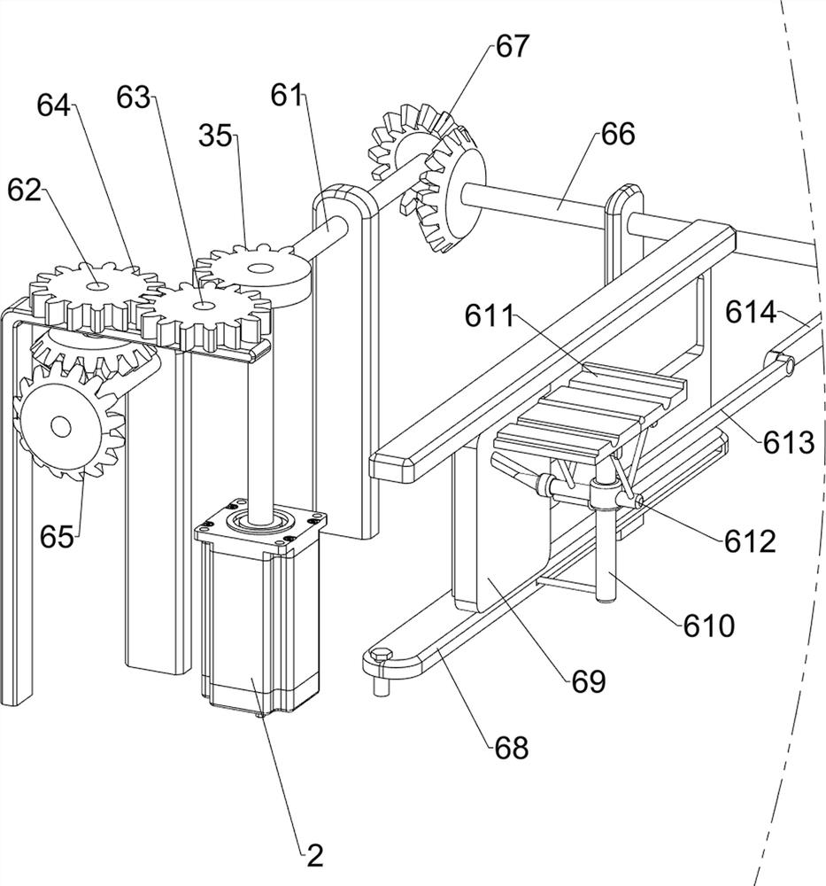
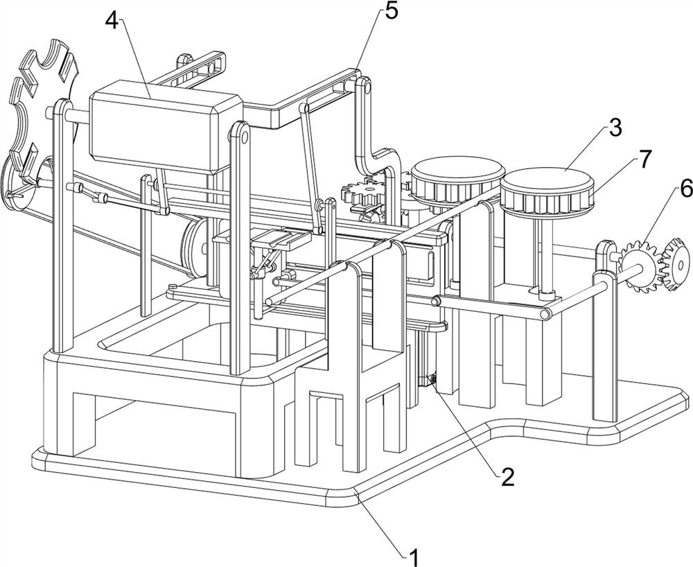
[0071]A ladder-type labeling network cable equipment for network engineering, such as figure 1 , figure 2 , image 3 , Figure 4 and Figure 7 As shown, it includes a bottom plate 1, a servo motor 2, a transmission mechanism 3, a turning mechanism 4, a feeding mechanism 5 and a labeling mechanism 6. A servo motor 2 is installed in the middle of the upper front side of the bottom plate 1, and a There is a transmission mechanism 3, a turning mechanism 4 is provided on the upper and rear side of the bottom plate 1, a feeding mechanism 5 is arranged on the upper middle of the bottom plate 1, and the feeding mechanism 5 cooperates with the turning mechanism 4, and a labeling mechanism 6 is arranged on the upper middle of the bottom plate 1, and the labeling mechanism Mechanism 6 cooperates with feeding mechanism 5.
[0072] When people paste labels on the network cables, it is impossible to achieve efficient identification of network cable equipment only by manually pasting th...
Embodiment 2
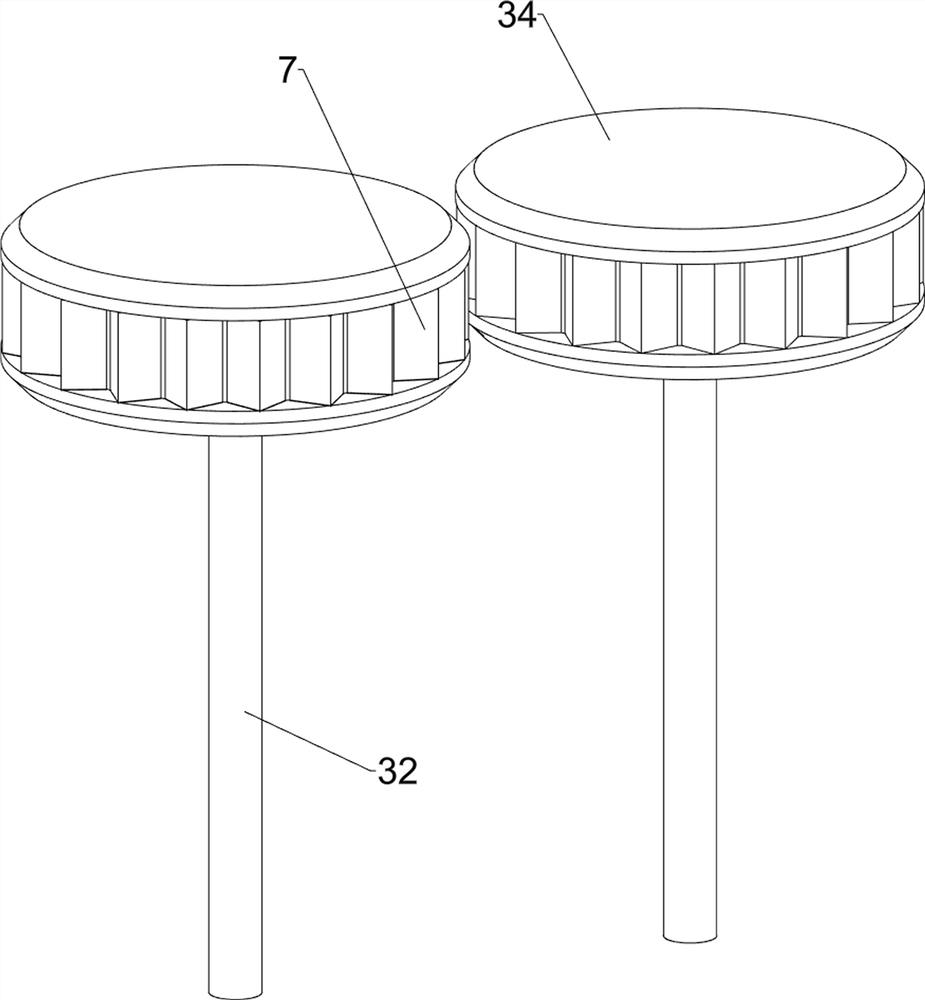
[0074] On the basis of Example 1, such as image 3 , Figure 4 , Figure 5 , Image 6 , Figure 7 , Figure 8 and Figure 9 As shown, the transmission mechanism 3 includes a first support frame 31, a first rotating shaft 32, a first spur gear 33, a guide wheel 34 and a missing gear 35, and the upper side of the output shaft of the servo motor 2 is provided with a missing gear 35, and the back of the bottom plate 1 The left side of the side is provided with a first support frame 31, and the left and right sides of the upper front side of the bottom plate 1 are symmetrically rotated to be provided with a first rotating shaft 32, and the upper sides of the two first rotating shafts 32 are provided with guide wheels 34, and the first rotating shaft 34 on the right side A first spur gear 33 is arranged on the upper side of a rotating shaft 32 , and the first spur gear 33 meshes with the missing gear 35 .
[0075] When people place the network cable on the first support frame ...
Embodiment 3
[0083] On the basis of Example 2, such as figure 1 , figure 2 and Figure 9 As shown, a fixed block 7 is also included, and the two guide wheels 34 are provided with a fixed block 7 .
[0084] When people put the network cable on the first support frame 31, and when the front side of the network cable contacts the guide wheel 34, then the servo motor 2 is turned on, and the output shaft of the servo motor 2 rotates to drive the missing gear 35 to rotate. When the missing gear 35 has a toothed side When meshing with the first spur gear 33, the missing gear 35 rotates to drive the first spur gear 33 to rotate, the first spur gear 33 rotates to drive the first rotating shaft 32 on the right side to rotate, and the first rotating shaft 32 on the right side rotates to drive the guide on the right side Wheel 34 rotates, and the guide wheel 34 of rotation drives fixed block 7 to rotate, and fixed block 7 rotates and drives network cable to move to the side, when network cable moves ...
PUM
 Abstract
Description
Claims
Application Information
 - R&D
- Intellectual Property
- Life Sciences
- Materials
- Tech Scout
- Unparalleled Data Quality
- Higher Quality Content
- 60% Fewer Hallucinations
Browse by: Latest US Patents, China's latest patents, Technical Efficacy Thesaurus, Application Domain, Technology Topic, Popular Technical Reports.
© 2025 PatSnap. All rights reserved.Legal|Privacy policy|Modern Slavery Act Transparency Statement|Sitemap|About US| Contact US: help@patsnap.com


