Compressor and heat pump equipment

A compressor and cylinder technology, applied in the field of compressors and rotary compressors, can solve the problems of cylinder inner diameter deformation, bearing damage clearance, affecting the performance and reliability of the compressor, and achieve safe, reliable, and stable performance. Effect

Pending Publication Date: 2021-02-12
ANHUI MEIZHI PRECISION MFG
View PDF0 Cites 0 Cited by
  • Summary
  • Abstract
  • Description
  • Claims
  • Application Information

AI Technical Summary

Problems solved by technology

[0003] In order to realize the above functions, it is necessary to install an air injection structure on the compressor. At present, the air injection structure is installed on the end surface of the cylinder or the end surface of the bearing, which will easily

Method used


Image

  • Compressor and heat pump equipment
  • Compressor and heat pump equipment
  • Compressor and heat pump equipment

Examples


Embodiment 1

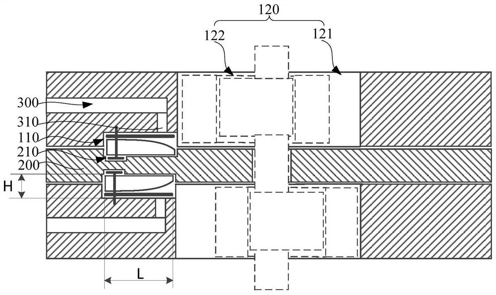
[0051] Such as figure 1 As shown, the present invention proposes a compressor, including: at least one cylinder assembly 100, each cylinder assembly 100 has a discharge cavity 121, and the end surface of each cylinder assembly 100 is provided with a first installation groove 110; a support member 200, It is arranged on one side of one cylinder assembly 100 in at least one cylinder assembly 100, and the end surface of the support member 200 is provided with a second installation groove 210, and the second installation groove 210 and the first installation groove 110 are arranged oppositely, and the first installation groove 110 and / or Or the second installation groove 210 communicates with the exhaust chamber 121; the air injection channel 300 is arranged on at least one cylinder assembly 100 and / or the support member 200, and the air injection channel 300 can communicate with the first installation groove 110 and the second installation groove 210; The one-way valve 400 is dis...

Embodiment 2

[0055] Such as figure 1 As shown, on the basis of the first embodiment above, the sum of the depth of the first installation groove 110 and the depth of the second installation groove 210 is H, and the depth of the first installation groove 110 is H1, which satisfies 0

[0056]In these embodiments, by taking the sum of the depth of the first installation groove 110 and the depth of the second installation groove 210 as H, the depth of the first installation groove 110 is H1, and 0

Embodiment 3

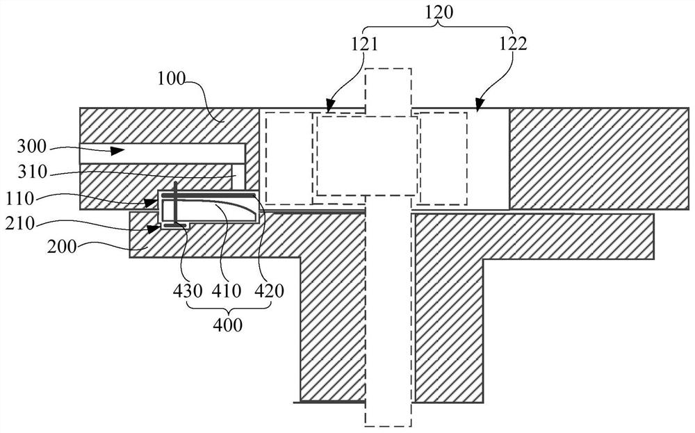
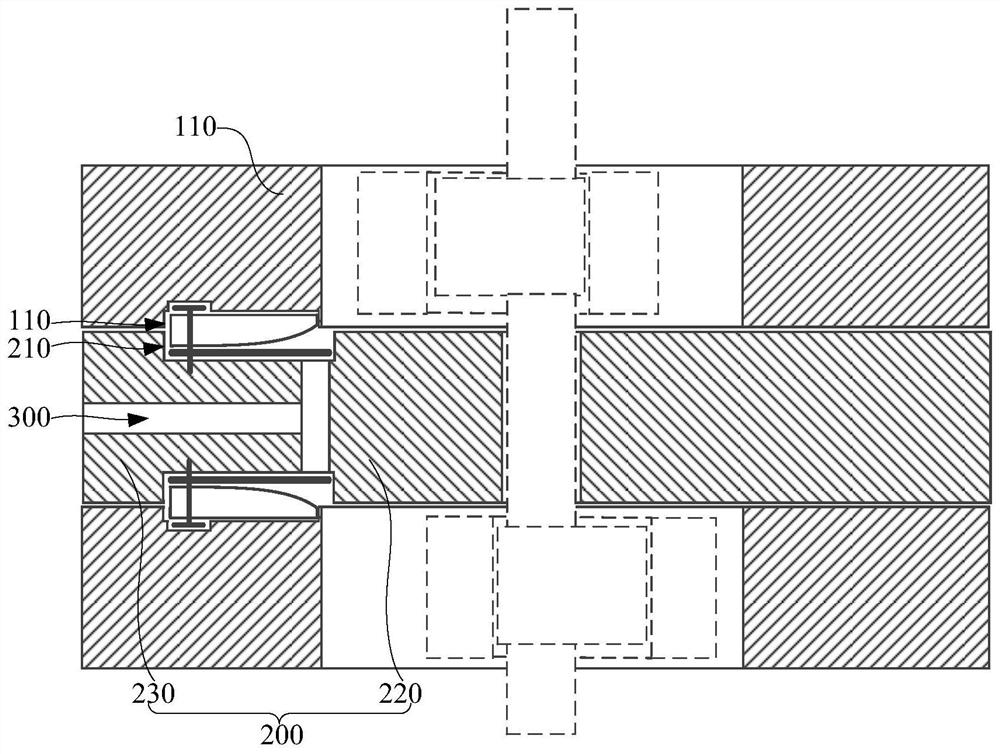
[0060] Such as figure 2 and image 3 As shown, on the basis of any of the above-mentioned embodiments, the first installation groove 110 and the second installation groove 210 are surrounded to form an air supply cavity; the air supply cavity includes a first cavity wall and a second cavity wall, and the first cavity wall and the second cavity wall The second cavity wall is the opposite cavity wall; the air injection end 310 is arranged on the first cavity wall, and the flow cross section of the air supply cavity decreases from the first cavity wall to the second cavity wall.

[0061] In these embodiments, the air supply chamber is formed by surrounding the first installation groove 110 and the second installation groove 210, so that the air supply chamber is partially set on the cylinder assembly 100 and partially on the support member 200, ensuring that the air cylinder assembly The structural strength and stability of 100 and support member 200 are not easy to be deformed...


PUM


Abstract

The invention provides a compressor and heat pump equipment. The compressor comprises at least one air cylinder assembly, a supporting piece, an air injection channel and the one-way valve, each air cylinder assembly is provided with an exhaust cavity, and a first mounting groove is formed in the end face of each air cylinder assembly; the supporting piece is arranged on one side of one air cylinder assembly in the at least one air cylinder assembly, a second mounting groove is formed in the end face of the supporting piece, the second mounting groove and the first mounting groove are oppositely formed, and the first mounting groove and/or the second mounting groove communicate/communicates with the exhaust cavity; the air injection channel is arranged on the at least one air cylinder assembly and/or the supporting piece, and the air injection channel can communicate with the first mounting groove and the second mounting groove; and the one-way valve is arranged in the first mounting groove and/or the second mounting groove. An air supplementing cavity is partially formed in the air cylinder assembly and partially formed in the supporting piece, the forming depth of the first mounting groove and the forming depth of the second mounting groove cannot be too large, the structural strength of the air cylinder assembly and the supporting piece are guaranteed, the stability is high,and use is safe and reliable.

Description

technical field [0001] The invention belongs to the technical field of rotary compressors, and in particular relates to a compressor and a heat pump device. Background technique [0002] Compressor is the core component of air-conditioning equipment, which can compress low-pressure refrigerant to form high-pressure gas. When the compressor is compressing the refrigerant, the medium-pressure and medium-temperature refrigerant whose external pressure is between the suction and discharge pressures is injected into the cylinder, which can increase the flow of suction and discharge, and improve the heating capacity and performance of the compressor. [0003] In order to realize the above functions, it is necessary to install an air injection structure on the compressor. At present, the air injection structure is installed on the end surface of the cylinder or the end surface of the bearing, which will easily cause the strength of the cylinder or bearing to decrease, resulting in ...

Claims


Application Information

Patent Timeline
IPC IPC(8): F04C29/12F25B30/02
CPCF04C29/12F04C29/126F25B30/02
Inventor 吴延平郭永祥程鹏
Owner ANHUI MEIZHI PRECISION MFG
Why Eureka
Try Eureka