
Support type vibration damping structure

A vibration-damping structure and support-type technology, which is applied in the direction of supporting machines, machine tables/brackets, springs/shock absorbers, etc.

Pending Publication Date: 2021-02-12
GREE ELECTRIC APPLIANCES INC
View PDF0 Cites 1 Cited by
  • Summary
  • Abstract
  • Description
  • Claims
  • Application Information

AI Technical Summary

Problems solved by technology

[0005] The purpose of the present invention is to provide a support type vibration damping structure to solve the technical problem that existing structures in the prior art are difficult to stably support vibrating objects while having better vibration isolation performance; many technical solutions provided by the present invention The many technical effects that can be produced by the optimal technical solution in the above are described in detail below

Method used


Image

  • Support type vibration damping structure
  • Support type vibration damping structure
  • Support type vibration damping structure

Examples


Embodiment 1

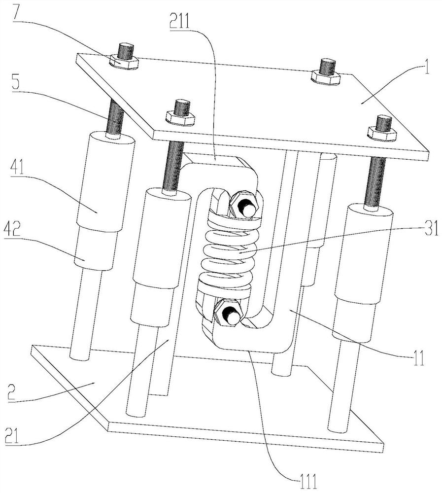
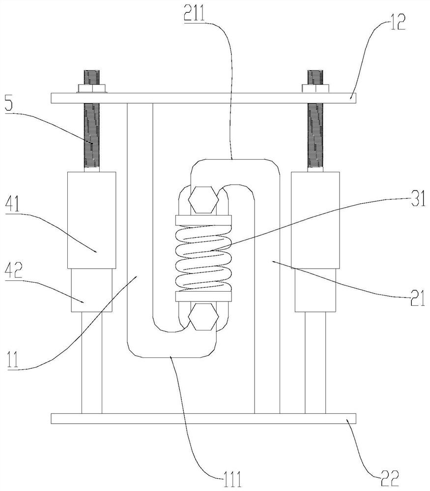
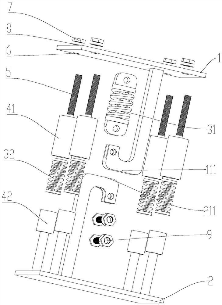
[0039] For the above problems, see Figure 1-Figure 3 As shown, this embodiment provides a support type vibration damping structure, including an upper base 1, a lower base 2 and an elastic assembly located between the two for reducing vibration, wherein: there is a structure on the upper base 1 for The first support end 111 that abuts against the lower base 2 after the elastic component is deformed, and / or, there is a second support end 211 on the lower base 2 that is used to abut against the upper base 1 after the elastic component is deformed, so as to limit The amount of deformation of the elastic component.

[0040] Wherein, the upper base 1 is used for contacting with the vibrating object, and the lower base 2 is used for contacting with the support, and the vibrating object and the support can be arranged in any adjacent arrangement up and down or left and right.

[0041] The above-mentioned elastic component for reducing vibration may be an elastically deformable cush...

Embodiment 2

[0070] As the main component for reducing vibration, the spring has a large deformation and good vibration damping effect; but at the same time, the spring is prone to lateral instability.

[0071] In view of the above problems, as an optional implementation, in this embodiment, there is a lateral limit mechanism 4 for limiting the lateral displacement of the second elastic portion 32 .

[0072] As an alternative implementation, see Figure 1-Figure 3 As shown, there is an outer casing 41 on either of the upper base 1 and the lower base 2, and an inner casing 42 exists on the other of the two, and the outer casing 41 is at least partly covered outside the inner casing 42. , and the second elastic portion 32 is located in the accommodation space formed by the inner casing 42 and the outer casing 41 , and the inner peripheral wall of the outer casing 41 is used to limit the lateral displacement of the second elastic portion 32 .

[0073] Such as Figure 1-Figure 3 Among them, ...


PUM


Abstract

The invention provides a supporting type vibration reduction structure, relates to the technical field of vibration reduction, and solves the technical problem that an existing structure difficultly has good vibration isolation performance while stably supporting a vibration animal. The supporting type vibration reduction structure comprises an upper base, a lower base and an elastic assembly located between the upper base and the lower base and used for reducing vibration, wherein the upper base is provided with a first supporting end used for abutting against the lower base after the elasticassembly deforms, and / or the lower base is provided with a second supporting end used for abutting against the upper base after the elastic assembly deforms so as to limit the deformation quantity ofthe elastic assembly. According to the supporting type vibration reduction structure, the elastic assembly elastically deforms to reduce vibration; through the structure that the first supporting endabuts against the lower base or the second supporting end abuts against the upper base, the deformation amount of the elastic assembly is limited, and the situation that the elastic assembly deformsexcessively and is difficult to support a vibrating object is prevented; and by means of the structure, vibration reduction and the stable supporting effect are combined, the structural stability is considered while vibration is reduced, and the structure can be used for supporting vibration animals to reduce vibration transmission.

Description

technical field [0001] The invention relates to the technical field of vibration reduction, in particular to a support type vibration reduction structure. Background technique [0002] In actual work, there are many devices that are supported and fixed in the form of brackets. For example, in the unit, the plate evaporator, water pump, etc. are directly located on the base bracket. [0003] The applicant found that there are at least the following technical problems in the prior art: On the one hand, the above-mentioned equipment components will generate water flow disturbance or vibration themselves during actual operation, and transmit it directly to adjacent components, which will cause adjacent components An increase in the vibration value of the measuring point. It is difficult to effectively reduce the transmission of vibration in the existing support structure; on the other hand, the existing vibration-damping structure has a large amount of deformation, such as a co...

Claims


Application Information

Patent Timeline
IPC IPC(8): F16F15/067F16M11/04
CPCF16F15/067F16M11/04
Inventor 范风强鲁涵锋周江峰陈东红范斌
Owner GREE ELECTRIC APPLIANCES INC
Learn More