Supercharge Your Innovation With Domain-Expert AI Agents!

Mechanical sealing part of sewage treatment equipment

A technology of sewage treatment equipment and mechanical seals, which is applied in the direction of engine seals, mechanical equipment, engine components, etc., can solve the problems of improvement, unobvious sealing effect, undisclosed connection scheme between static ring and dynamic ring, etc., and achieve enhanced deformation ability, strengthen the sealing effect, and use the effect of strong flexibility

Inactive Publication Date: 2021-02-12
WUHU ZHONGTIAN SEALS
View PDF2 Cites 0 Cited by
  • Summary
  • Abstract
  • Description
  • Claims
  • Application Information

AI Technical Summary

Problems solved by technology

[0003] For example, the application number is CN201420528957.9, which discloses a switchable mechanical seal, which solves the problem that the mechanical seal can be switched and used when the external pressure is different, and increases the service life of the mechanical seal. The main points of the technical solution are The movable block is hinged to the fixed base; the adjustment mechanism includes a first linkage rod and a second linkage rod; the first linkage rod includes a first connection end and a second connection end, the first connection end is hinged to the fixed base, and the second connection end Sliding connection with the movable block; the movable block is provided with a limit mechanism; one end of the second linkage rod is hinged with the middle part of the first linkage rod, and the other end of the second linkage rod passes through the fixed base; the fixed base is provided with The fixing mechanism for fixing the second linkage rod, this kind of switchable mechanical seal, when the external pressure changes, the auxiliary seal and the static ring can be adjusted through the linkage action of the first linkage rod, the second linkage rod and the movement. The contact area is adjusted to increase the service life of the mechanical seal, but this kind of switchable mechanical seal does not disclose an effective connection scheme between the static ring and the dynamic ring
[0004] For example, the application number is CN201420526641.6, which discloses a mechanical seal, which solves the technical problems of cumbersome and inconvenient installation of mechanical seals in the prior art, and the technical problem that the sealing effect is not obvious when used. The moving ring seat on the rotating shaft, the moving ring connected to the moving ring seat, the auxiliary seal connected to the moving ring, and the static ring connected to the auxiliary sealing member, the moving ring is close to the end of the moving ring seat and relative to the rotating shaft A first groove is provided on one side of the surface, a through hole is provided on the moving ring seat corresponding to the first groove, a second groove is provided on the surface of the moving ring corresponding to the through hole, and a second groove is provided in the second groove The clamping block, an elastic piece is arranged between the clamping block and the second groove
This kind of mechanical seal is equipped with elastic parts and clamping blocks to facilitate the installation, disassembly and maintenance of the mechanical seal. The auxiliary seal is provided with protrusions, and the moving ring and the static ring are provided with protrusions on the side corresponding to the auxiliary seal. The matching groove improves the sealing effect of the mechanical seal, but this kind of seal does not disclose how to improve the connection between the static ring and the moving ring

Method used


Image

  • Mechanical sealing part of sewage treatment equipment
  • Mechanical sealing part of sewage treatment equipment
  • Mechanical sealing part of sewage treatment equipment

Examples


Embodiment 1

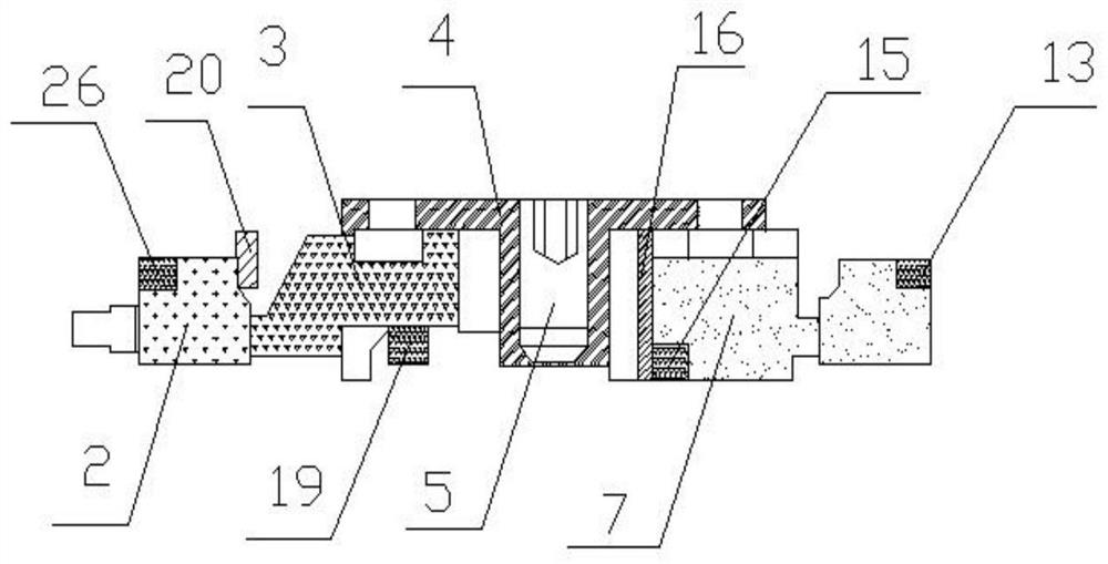
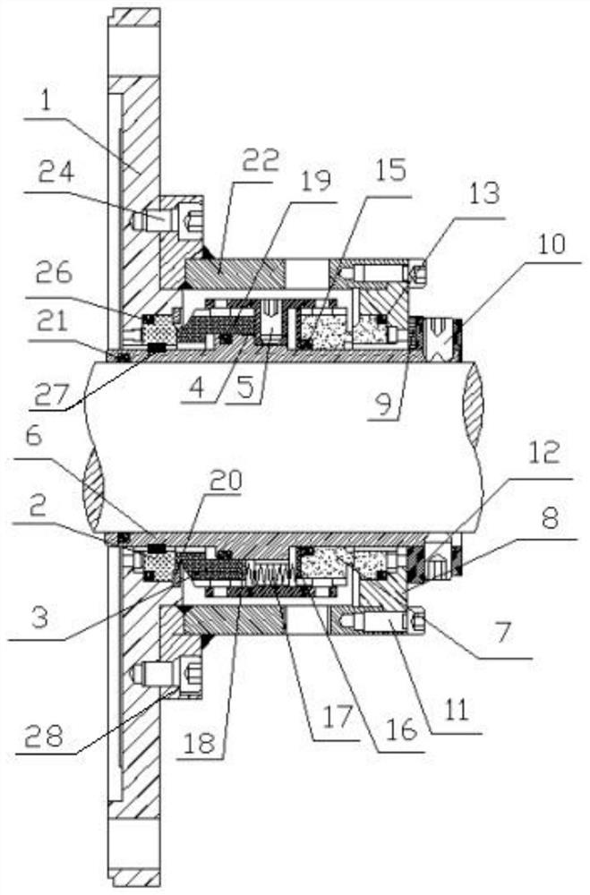
[0020] Such as image 3 with Figure 4 As shown, a mechanical seal for sewage treatment equipment includes a static ring assembly, a moving ring assembly, a gland assembly, a spring assembly, a medium end gland 1 and a mechanical seal shaft sleeve 6, and the medium end gland 1 is connected to the mechanical seal The shaft sleeve 6 is fixedly connected, and the static ring assembly includes the static ring 2 at the medium end, the static ring 26 at the atmospheric end, the static ring seal ring 13 at the atmospheric end located on the static ring 26 at the atmospheric end, and the static ring 2 at the medium end. The static ring seal ring 27 at the medium end, the static ring 2 at the medium end is connected to the gland 1 at the medium end, the positioning ring 9 is connected to the static ring 26 at the atmospheric end, and the static ring assembly is fixed, which can ensure the sealing of the device The positioning ring 9 is connected with the transmission ring 12 fixed on ...

Embodiment 2

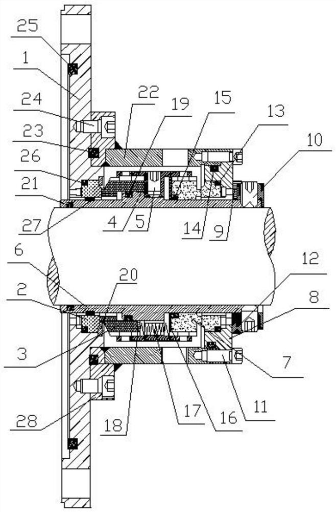
[0024] Such as figure 1 with figure 2 As shown, a mechanical seal for sewage treatment equipment includes a static ring assembly, a moving ring assembly, a gland assembly, a spring assembly, a medium end gland 1 and a mechanical seal shaft sleeve 6, and the medium end gland 1 is connected to the mechanical seal The shaft sleeve 6 is fixedly connected, and the static ring assembly includes the static ring 2 at the medium end, the static ring 26 at the atmospheric end, the static ring seal ring 13 at the atmospheric end located on the static ring 26 at the atmospheric end, and the static ring 2 at the medium end. The static ring seal ring 27 at the medium end, the static ring 2 at the medium end is connected to the gland 1 at the medium end, the positioning ring 9 is connected to the static ring 26 at the atmospheric end, and the static ring assembly is fixed, which can ensure the sealing of the device The positioning ring 9 is connected with the transmission ring 12 fixed on ...


PUM


Abstract

The invention discloses a mechanical sealing part of sewage treatment equipment and relates to the field of mechanical sealing. The mechanical sealing part comprises a static ring assembly, a movablering assembly, a medium end gland and a mechanical sealing shaft sleeve, wherein the medium end gland is fixedly connected with the mechanical sealing shaft sleeve; the static ring assembly comprisesa medium end static ring, an atmosphere end static ring, an atmosphere end static ring sealing ring arranged on the atmosphere end static ring and a medium end static ring sealing ring arranged on themedium end static ring; the medium end static ring is connected with the medium end gland; and the movable ring assembly comprises a medium end movable ring connected with the medium end static ring,an atmosphere end movable ring connected with the atmosphere end static ring, a medium end movable ring sealing ring arranged on the medium end movable ring and an atmosphere end movable ring sealingring arranged on the atmosphere end movable ring. According to the mechanical sealing part of the sewage treatment equipment, the mechanical sealing performance can be effectively guaranteed throughcooperation of the medium end static ring, the atmosphere end static ring and a spring assembly on the static ring assembly.

Description

technical field [0001] The invention relates to the field of mechanical seals, in particular to a mechanical seal for sewage treatment equipment. Background technique: [0002] In the current mechanical seals, the contact surface between the moving ring and the static ring is generally a circular plane, and the moving ring is tightly attached to the static ring through the action of the elastic member. The pressure on the contact surface between the moving ring and the static ring is not very high. When the pressure of the external environment changes greatly, the leakage will increase. Therefore, it is necessary to improve the position of the static ring and the moving ring. The tightness of the device. [0003] For example, the application number is CN201420528957.9, which discloses a switchable mechanical seal, which solves the problem that the mechanical seal can be switched and used when the external pressure is different, and increases the service life of the mechanic...

Claims


Application Information

Patent Timeline
Patent Type & Authority Applications(China)
IPC IPC(8): F16J15/34
CPCF16J15/3452F16J15/3464
Inventor 江波赵长红王旭东
Owner WUHU ZHONGTIAN SEALS
Features
  • R&D
  • Intellectual Property
  • Life Sciences
  • Materials
  • Tech Scout
  • Unparalleled Data Quality
  • Higher Quality Content
  • 60% Fewer Hallucinations
Learn More