
Cooling machine

A cooling machine and blade group technology, applied in the field of cooling machines, can solve problems such as poor cooling effect, low cooling efficiency, and uneven cooling of materials, and achieve the effect of ensuring material quality, high cooling efficiency, and good cooling effect

Pending Publication Date: 2021-02-12
江苏博涛智能热工股份有限公司
View PDF0 Cites 0 Cited by
  • Summary
  • Abstract
  • Description
  • Claims
  • Application Information

AI Technical Summary

Problems solved by technology

In the prior art, the spiral propulsion method with the same direction of rotation is usually used for cooling. Obviously, it has the following defects: first, the cooling efficiency is low due to the heat transfer and heat dissipation through the shell; The method makes the external material cool faster, while the internal material flow is less, resulting in uneven cooling of the material, resulting in poor cooling effect, poor quality of material or even scrapping

Method used


Image

  • Cooling machine
  • Cooling machine

Examples


Embodiment Construction

[0018] The present invention will be further described below in conjunction with the accompanying drawings and specific embodiments, so that those skilled in the art can better understand the present invention and implement it, but the examples given are not intended to limit the present invention.

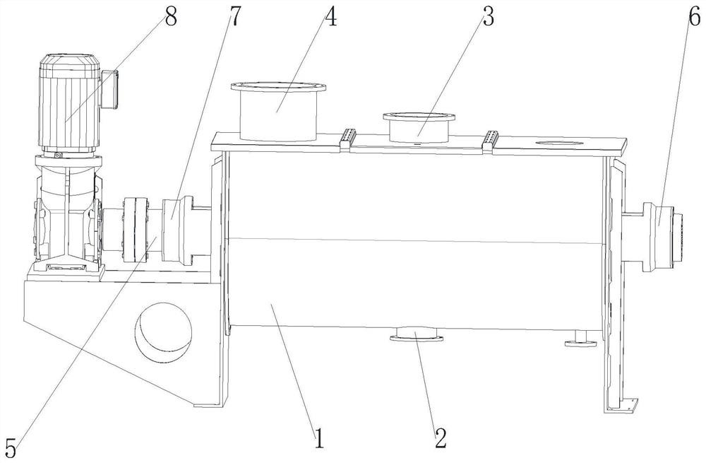
[0019] refer to figure 1 and figure 2 Shown: a cooling machine, including a shell 1, in this embodiment, the shell 1 is made of stainless steel. The center of the bottom of the housing 1 is provided with a discharge port 2, and the top is provided with a feed port 3 opposite to the discharge port 2, and is communicated with a fan (not shown in the figure) through the air duct 4, and the inside of the housing 1 A horizontally arranged stirring shaft 5 is installed for rotation, and both ends of the stirring shaft 5 protrude from the housing 1, and one end is connected to the first bearing seat 6, and the other end is connected to the driving device 8 through the second bearing se...


PUM


Abstract

The invention discloses a cooling machine. The cooling machine comprises a shell body, a discharging port is formed in the center of the bottom of the shell body, a feeding port opposite to the discharging port is formed in the top of the shell body, the shell body is communicated with a draught fan through an air duct, a stirring shaft is transversely and rotationally installed in the interior ofthe shell body, the two ends of the stirring shaft both extend out of the shell body, one end of the stirring shaft is connected to a first bearing seat, the other end is in transmission connection with a driving device through a second bearing seat, a plurality of stirring rods are vertically arranged on the stirring shaft at uniform intervals in a penetrating manner, first outer spiral blade groups, first inner spiral blade groups, second inner spiral blade groups and second outer spiral blade groups, the rotating directions of the first inner spiral blade groups are opposite to the rotating directions of the first outer spiral blade groups, the second inner spiral blade groups and the second outer spiral blade groups are symmetrical to the centers of the first inner spiral blade groupsand the centers of the outer spiral blade groups with respect to the axial directions of the stirring rods; and the tail parts of the first inner spiral blade groups and the tail parts of the first outer spiral blade groups and the head parts of the second inner spiral blade groups and the head parts of the second outer spiral blade groups are connected to the same stirring rod located right above the discharging port in a staggered manner. The cooling machine solves the technical problem of how to efficiently and uniformly cool materials.

Description

technical field [0001] The invention relates to the technical field of cooling equipment, in particular to a cooling machine. Background technique [0002] Material cooling is one of the important links in the process of high temperature material handling. In the prior art, the spiral propulsion method with the same direction of rotation is usually used for cooling. Obviously, it has the following defects: first, the cooling efficiency is low due to the heat transfer and heat dissipation through the shell; The method makes the external material cool faster, while the internal material flow is less, resulting in uneven cooling of the material, resulting in poor cooling effect, poor quality of the material or even scrapping. Contents of the invention [0003] The technical problem to be solved by the present invention is to provide a cooling machine to achieve the purpose of high cooling efficiency, good cooling effect and effective guarantee of material quality. [0004] ...

Claims


Application Information

Patent Timeline
IPC IPC(8): F25D1/00F25D25/00F25D17/08F25D17/04F25D23/06
CPCF25D1/00F25D17/042F25D17/08F25D23/062F25D25/00
Inventor 霍李均吕张忠施卫
Owner 江苏博涛智能热工股份有限公司
Features
  • Generate Ideas
  • Intellectual Property
  • Life Sciences
  • Materials
  • Tech Scout
  • Unparalleled Data Quality
  • Higher Quality Content
  • 60% Fewer Hallucinations
Learn More