Heat-shrinkable plastic member, composite preform, and composite container

A preform, heat shrinking technology, applied in rigid containers, containers, household containers, etc., can solve problems such as limited means, and achieve the effect of improving production efficiency and improving ease of insertion

Active Publication Date: 2021-02-12
MITSUBISHI CHEM CORP +1
View PDF16 Cites 0 Cited by
  • Summary
  • Abstract
  • Description
  • Claims
  • Application Information

AI Technical Summary

Problems solved by technology

[0005] However, in the conventional biaxial stretch blow molding method, the preform is usually simply molded into a container shape
Therefore, in the case of imparting various functions or properties (barrier properties, heat retention, etc.) to the container, for example, changing the material constituting the preform is limited.

Method used


Image

  • Heat-shrinkable plastic member, composite preform, and composite container
  • Heat-shrinkable plastic member, composite preform, and composite container
  • Heat-shrinkable plastic member, composite preform, and composite container

Examples


Embodiment 1

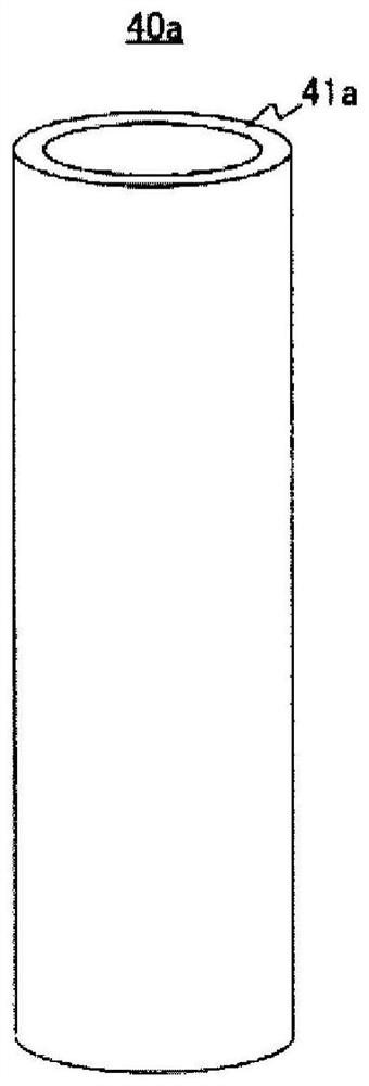
[0160] Using a ring-shaped die, an energy storage mold made of Himilan 1706 (manufactured by Dupont-Mitsui Polychemical Co., Ltd., MFR 0.9 g / 10 minutes, 25° C. Volume 3.8×10 8 Pa) 95% by mass, Win-Tech WFX4TA (manufactured by Japan Polypropylene Co., Ltd., metallocene polypropylene, MFR7.0g / 10min, storage modulus 1.0×10 in 25°C environment) as olefin resin (B) 9 Pa) The mixture compounded at a ratio of 5% by mass was melt-extruded to form an undrawn tube with an inner diameter of 16.6 mm, and then the undrawn tube was heated with hot water, pressurized with compressed gas from the inside of the tube, and stretched. Stretching, thereby producing a bottomless cylindrical heat-shrinkable plastic part. In addition, the heat-shrinkable plastic member had an inner diameter of 28.7 mm and a thickness of 307 μm.

Embodiment 2

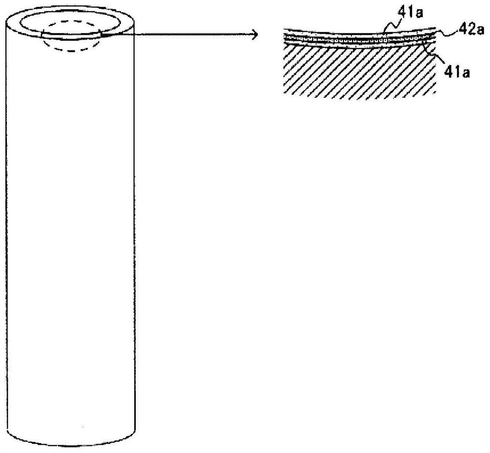
[0162]For the outermost layer, a mixture of Himilan 1706 95% by mass as the ionomer resin (A) and 5% by mass of Win-TechWFX4TA as the olefin resin (B) was used, and 100% by mass for the adhesive layer The polyolefin-based adhesive resin (Admer SF731, manufactured by Mitsui Chemicals Co., Ltd.), the intermediate layer uses a mixture of ethylene-vinyl alcohol copolymer (EVALSP482B, manufactured by KURARAY Co., Ltd.) in a ratio of 100% by mass as a gas barrier layer , using a 5-layer ring die, the three materials were melted and extruded through a single-screw extruder to form an unstretched tube with an inner diameter of 18.3 mm, and then heated with hot water to heat the unstretched tube from the inside of the tube. Compressed gas is pressurized and stretched to produce a bottomless cylindrical heat-shrinkable plastic member. In addition, the heat-shrinkable plastic member had an inner diameter of 28.7 mm and a thickness of 345 μm (outermost layer 132 μm, adhesive layer 17 μm, ...


PUM

PropertyMeasurementUnit
storage modulusaaaaaaaaaa

Abstract

Provided is a heat-shrinkable plastic member provided to at least part of the outside of a preform comprising a mouth, a body connected to the mouth, and a bottom connected to the body, wherein the heat-shrinkable plastic member is characterized by being provided at least with a layer containing an ionomer resin (A) and an olefin resin (B) as essential components, having a storage modulus of 4.0 x10⁸ Pa or higher in a 25 DEG C environment, and having a dynamic friction coefficient of 1.1 or lower with respect to the preform, whereby it is possible to markedly improve the ease of insertion ofthe preform.

Description

technical field [0001] The present invention relates to a heat-shrinkable plastic part, a composite preform provided with the heat-shrinkable plastic part, and a composite container which is a blow-molded product of the composite preform. Background technique [0002] Recently, plastic containers are generally used as containers for containing content liquids such as food and beverages. [0003] Such a plastic container containing a liquid content can be produced by inserting a preform into a mold and then biaxially stretching blow molding it (biaxially stretching blow molding method). [0004] In addition, in the past, in the manufacture of plastic containers, for example, preforms made of single-layer materials, multi-layer materials, or blended materials such as polyethylene terephthalate (PET) or polypropylene (PP) have been used. body. [0005] However, in the conventional biaxial stretch blow molding method, usually, the preform is simply molded into a container shap...

Claims


Application Information

Patent Timeline
Patent Type & Authority Applications(China)
IPC IPC(8): B29C61/02B29C49/22B32B27/28B32B27/32
CPCB29C49/0005B29C49/02B29C49/22B29C61/0616B29C61/02B29C63/42B32B1/08B32B1/02B32B27/32B32B27/308B32B27/327B32B27/325B32B27/306B32B27/36B32B27/34B32B27/20B32B27/22B32B27/08B32B7/12B32B23/08B65D23/0864B32B2439/00B32B2597/00B32B2307/402B32B2307/412B32B2307/71B32B2307/7244B32B2307/732B32B2307/736B32B2307/744B29K2067/003B29K2995/0049B29K2105/0094B29K2995/0012B29K2995/0097B29K2023/12B29L2031/7158B32B3/08B32B27/302B32B2270/00B32B3/30B32B3/02B32B23/04B32B27/28B65D1/0223
Inventor 池田启太小田原功治三轮雅树桥本大地须贺勇介宫胁琢磨
Owner MITSUBISHI CHEM CORP
Why Eureka
Try Eureka