Tendon suturing system for joint replacement

A joint replacement and tendon technology, applied in the field of medical surgery, can solve the problems that tendon suture products cannot be fixed in an effective position, difficult tendon suture surgery, etc., to achieve the effect of ensuring the continuity of the tendon and benefiting the health of the tendon

Active Publication Date: 2021-02-19
GUANGDONG STABLE MEDICAL TECH CO LTD
View PDF10 Cites 0 Cited by
  • Summary
  • Abstract
  • Description
  • Claims
  • Application Information

AI Technical Summary

Problems solved by technology

At present, the tendon repair technology in general surgery is mainly to fix the sutured tendon on the para-articular bone with screws or other instruments. Therefore, in joint replacement, conventional tendon repair mesh, tendon repair sleeve and artificial Tendon suture products such as sutured tendon kits will not stay in place, making it difficult to perform effective tendon sutures after joint replacement

Method used


Image

  • Tendon suturing system for joint replacement
  • Tendon suturing system for joint replacement
  • Tendon suturing system for joint replacement

Examples


Embodiment 1

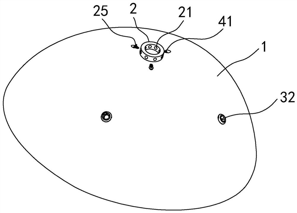
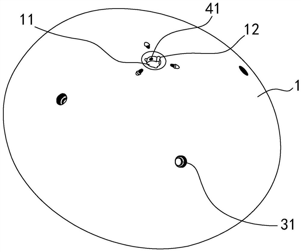
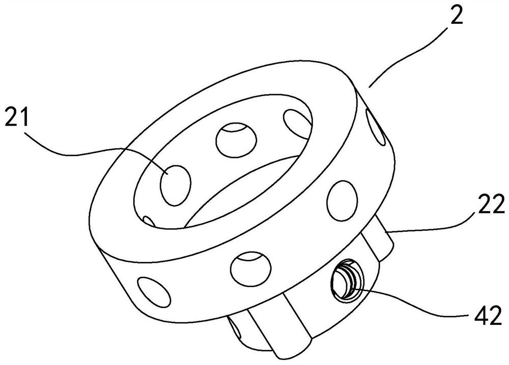
[0048] refer to Figure 1 to Figure 6 , the present invention is a kit, including a joint prosthesis 1, a stapler 2, a locking structure, a bone thread system, and a shift fork 5. The locking structure adopts thread as the main connection means. The joint prosthesis 1 has an outer convex surface, and an installation groove 11 is provided at the apex position of the outer convex surface close to the geometric shape or directly at the apex itself, and the stapler 2 is embedded in the installation groove 11 and then fixed, the stapler The upper end of the prosthesis 2 is used for binding and connecting with the artificial tendon, and the joint prosthesis 1 is connected and fixed with the external backbone through a bone thread system.

[0049] The joint prosthesis 1 can be bionically printed using 3D printing technology, so that the shape and accuracy of the product can be guaranteed, and at the same time, each threaded hole position can also be printed synchronously, and the ma...

Embodiment 2

[0055] refer to Figure 7 to Figure 9 , Embodiment 2 is basically the same as Embodiment 1, but the locking structure adopts elastic buckle as the main connection means. Specifically, the upper part of the second end of the stapler 2 is connected to the lower surface of the first end of the stapler 2 and the outer diameter of the second end is smaller than the outer diameter of the first end, thereby leaving an annular surface, A positioning column 23 extending downward is provided on the annular surface, and a positioning hole 13 matching the positioning column 23 is provided on the bottom surface of the installation groove 11. The functions of the positioning hole 13 and the positioning column 23 are the same as those in the first embodiment. Notches 12 are similar to positioning ribs 22 . And the bottom of the second end is provided with the elastic connecting cap 24 that is up big and down little down umbrella shape, and elastic connecting cap 24 is elastic material, and ...


PUM


Abstract

The invention discloses a tendon suturing system for joint replacement, which comprises a joint prosthesis, a suturing instrument, a locking structure and a bone setting thread system, wherein the joint prosthesis is provided with an outer convex surface, and a mounting groove is formed in the outer convex surface; the stitching instrument is provided with a first end and a second end, a stitchinghole is formed in the first end, and the shape of the second end is matched with that of the mounting groove, so that the second end can be embedded into the mounting groove; the locking structure isused for fixing the stitching instrument on the joint prosthesis without loosening; and the bone setting thread system is used for fixing the joint prosthesis to an external backbone. The stitching instrument and the joint prosthesis can be effectively combined, the combined assembly body is fixed on the joint backbone, and meanwhile, the tendon continuity of a wounded part is smoothly guaranteed, so that the postoperative tendon rehabilitation is facilitated, and the postoperative tendon is not displaced. The tendon suturing system is used in the joint replacement.

Description

technical field [0001] The invention relates to the field of medical operations, in particular to a tendon suture system for joint replacement. Background technique [0002] Joint replacement is a surgical operation in which a joint prosthesis imitating an artificial joint is placed in the body to replace a diseased joint in order to relieve pain and restore joint function. Tendons are sutured and repaired during joint replacement surgery. At present, the tendon repair technology in general surgery is mainly to fix the sutured tendon on the para-articular bone with screws or other instruments. Therefore, in joint replacement, conventional tendon repair mesh, tendon repair sleeve and artificial Tendon suturing products, such as suture tendon kits, will not stay in place, making it difficult to perform effective tendon suturing procedures after joint replacement. Contents of the invention [0003] The purpose of the present invention is to provide a tendon suture system fo...

Claims


Application Information

Patent Timeline
Patent Type & Authority Applications(China)
IPC IPC(8): A61B17/04
CPCA61B17/0491A61B2017/0403A61B2017/0414A61B2017/0445A61B2017/0464
Inventor 彭文玉培良陈康黎志炼周邦桦陈柔合
Owner GUANGDONG STABLE MEDICAL TECH CO LTD
Why Eureka
Try Eureka