A paint crossing device and paint crossing method for valve processing

A valve and body technology, applied in the field of varnishing devices for valve processing, can solve the problems of uneven varnishing, easy accumulation of paint on contact points, etc., and achieve the effects of ensuring quality and efficiency, avoiding static solidification, and avoiding dead ends.

Active Publication Date: 2021-09-07
林仙夫
View PDF7 Cites 0 Cited by
  • Summary
  • Abstract
  • Description
  • Claims
  • Application Information

AI Technical Summary

Problems solved by technology

The paint-transfer equipment for valve processing in the above-mentioned patents has the following disadvantages: the valve body undergoes paint-transfer several times under the up-and-down reciprocating motion of the transmission belt, and the surface of the valve is still in contact with the conveyor frame during the paint-transfer process, and paint is easy to accumulate at the contact points, resulting in Uneven paint

Method used


Image

  • A paint crossing device and paint crossing method for valve processing
  • A paint crossing device and paint crossing method for valve processing
  • A paint crossing device and paint crossing method for valve processing

Examples


Embodiment 1

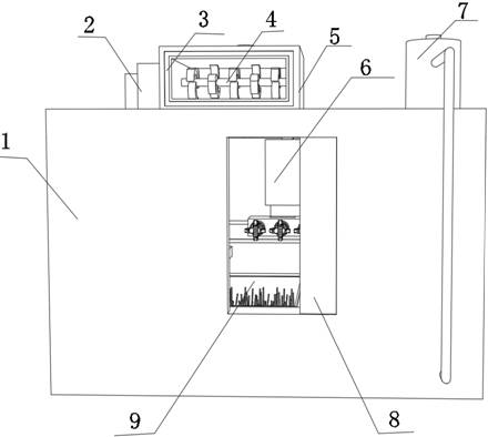
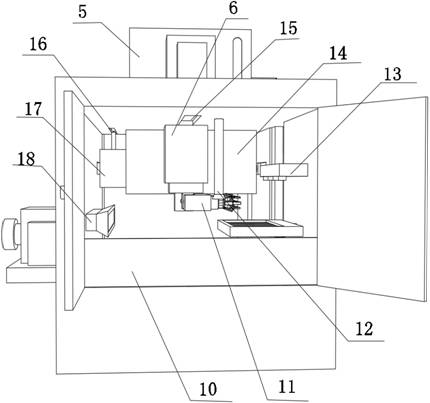
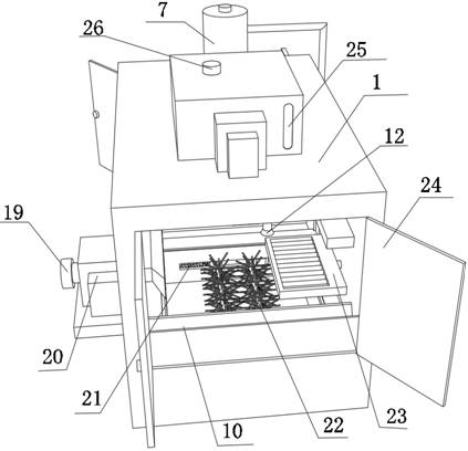
[0040] A paint crossing device for valve processing, such as Figure 1-5 As shown, including the body 1, the top inner wall of the body 1 is provided with a first electric chute 15, the inner wall of the first electric chute 15 is slidably connected with a hydraulic cylinder 6 through a slider, and the extension end of the hydraulic cylinder 6 is connected through a connecting column. The connecting seat 11 is rotatably connected, and the bottom inner wall of the connecting seat 11 is fixed with a third motor 40 by bolts. The inner wall of one side of the connecting seat 11 is connected with three gears 32 through the rotating shaft, and the outer walls of the three gears 32 mesh with each other. One of the gears The input end of 32 is connected with the output end of the 3rd motor 40 through connecting shaft, and one side outer wall of connection base 11 is connected with three clamping hands 41 through rotating shaft rotation, and the input end of three clamping hands 41 is c...

Embodiment 2

[0046] A kind of embodiment 1 is used for the method for crossing the paint of valve processing with the paint crossing device, such as Figure 1-5 shown, including the following steps:

[0047] S1: adding paint to the first material box 5;

[0048] S2: Place the valve in the net cage 17, start the cleaning spray 28 and the second motor 31, drive the net cage 17 to clean and dry the water during the rotation process;

[0049] S3: Take out the cleaned valve, and fix one end of the valve with the clamping hand 41;

[0050] S4: Start the hydraulic cylinder 6 to drive the valve to reciprocate up and down to paint, and the brush wheel 22 passively paints the valve;

[0051] S5: start the blower fan 20 and the third motor 40, and dry the outside air after the valve after the painting is filtered out of impurities during the rotation process;

[0052] S6: Put the painted valve on the holding frame 23, spray and dry one end of the unpainted valve;

[0053] S7: Open the second box do...


PUM


Abstract

The invention discloses a paint crossing device and a paint crossing method for valve processing, and relates to the technical field of valve processing; in order to solve the problem of easy accumulation of paint at contact points; the device includes a body, and the top inner wall of the body is provided with a first motor Chute, the inner wall of the first electric chute is provided with a hydraulic cylinder, the extension end of the hydraulic cylinder is connected to the connecting seat through the connecting column, the bottom inner wall of the connecting seat is provided with a third motor, and the inner wall of one side of the connecting seat is provided with three gears The paint-crossing method of the device includes the following steps: adding paint to the first material box; placing the valve in the net cage, starting the cleaning spray and the second motor, and driving the net cage to complete cleaning and drying during the rotation process; moisture. In the wind blowing process of the present invention, the valve rotates continuously at the same time to speed up the solidification of the valve after feeding, and there is no point of force during the solidification of the valve feeding position, so there will be no accumulation of paint, ensuring the quality and efficiency of the paint.

Description

technical field [0001] The invention relates to the technical field of valve processing, in particular to a paint-transfer device and a paint-transfer method for valve processing. Background technique [0002] Valves can be used to control the flow of various types of fluids such as air, water, steam, various corrosive media, mud, oil, liquid metal and radioactive media. Valves are also divided into cast iron valves, cast steel valves, and stainless steel valves according to their materials. Chromium molybdenum steel valves, chrome molybdenum vanadium steel valves, duplex steel valves, plastic valves, non-standard custom valves, etc. In order to protect the valve, it is necessary to spray paint on the valve to increase the corrosion resistance of the valve. The existing valve painting device has a bad working environment in the workshop. During the painting work, it is necessary to manually rotate the shell to ensure that all directions of the shell are sprayed evenly, whic...

Claims


Application Information

Patent Timeline
Patent Type & Authority Patents(China)
IPC IPC(8): B05C1/02B05C13/02B05B16/20B05B15/25B08B3/02B08B13/00B05C9/12B05C9/10B05D3/04B05C3/02B05C3/00B05B15/555
CPCB05C1/02B05C3/005B05C3/02B05C9/10B05C9/12B05C13/02B05D3/0406B08B3/022B08B13/00B05B15/25B05B15/555B05B16/20
Inventor 舒瑞
Owner 林仙夫
Why Eureka
Try Eureka