
Carrier manipulator for front shell of Bluetooth headset charging box

A Bluetooth earphone and charging box technology, applied in the field of manipulators, can solve the problems of low accuracy and low assembly efficiency, and achieve high assembly efficiency, prevent deviation, and good assembly effect

Active Publication Date: 2021-02-19
江西立讯智造有限公司
View PDF11 Cites 3 Cited by
  • Summary
  • Abstract
  • Description
  • Claims
  • Application Information

AI Technical Summary

Problems solved by technology

[0002] The wireless bluetooth earphone is a recent new type of digital product, small and exquisite, easy to use, the same bluetooth earphone charging box is also small in size, the bluetooth earphone charging box is usually the front shell and the back shell snapped together, but due to the small size, and The surface is relatively smooth. If manual assembly is used, the accuracy is not high and the assembly efficiency will be very low.

Method used


Image

  • Carrier manipulator for front shell of Bluetooth headset charging box
  • Carrier manipulator for front shell of Bluetooth headset charging box
  • Carrier manipulator for front shell of Bluetooth headset charging box

Examples


Embodiment 1

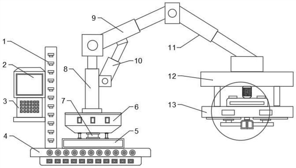
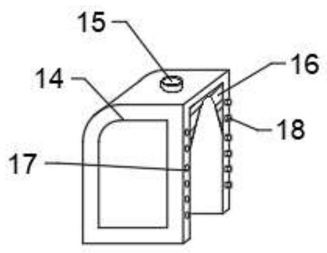
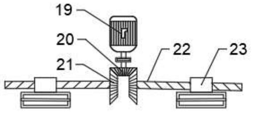
[0022] see Figure 1~4 , in an embodiment of the present invention, a carrier manipulator for the front case of a Bluetooth earphone charging box, including a mounting plate 1; a display screen 2 and an operation panel 3 are installed on the mounting plate 1; the mounting plate 1 is mounted on a base 4 The top of the base 4 is equipped with a driving box 5; the driving box 5 is connected to the installation box 6 through a rotating mechanism; a No. 1 hydraulic rod 8 is installed on the described installation box 6; the No. 1 hydraulic rod 8 is hinged to two One end of No. 9 hydraulic rod 9; the other end of No. 2 hydraulic rod 9 is hinged No. 4 hydraulic rod 11; No. 3 hydraulic rod 10 is hinged between No. 1 hydraulic rod 8 and No. 2 hydraulic rod 9; A working plate 12 is installed on the bottom of the hydraulic rod 11; a working device 13 is installed on the bottom of the working plate 12.

[0023] Further, the rotating mechanism includes a servo motor; the servo motor is co...

Embodiment 2

[0029] see figure 2 , the bottom of the installation box 6 is fixedly equipped with a slide bar; the slide bar is at least evenly provided with four; the bottom end of the slide bar is provided with a slider; the bottom end of the slide block is provided with a ball; The top of the drive box 5 has a circular track corresponding to the slide block; the inner bottom of the circular track is provided with a ball groove corresponding to the ball; through the setting of the slide bar, balls, slider, circular track and ball groove, the working device 13 can be rotated stably , to prevent assembly deviation and ensure assembly accuracy.

[0030]The working principle of the present invention is: through the setting of servomotor, gearbox, gear and rotating column 7, can rotate work implement 13, convenient to use; The setting of the No. 4 hydraulic rod 11 can adjust the air position of the operation panel 3, which is convenient for assembly; through the mutual cooperation of the cla...


PUM


Abstract

The invention discloses a carrier manipulator for a front shell of a Bluetooth headset charging box. The carrier manipulator comprises a mounting plate, wherein a display screen and an operation panelare mounted on the mounting plate; the mounting plate is mounted at the top of a base; a driving box is mounted at the top end of the base; the driving box is connected with a mounting box through arotating mechanism; a first hydraulic rod is mounted on the mounting box; the first hydraulic rod is hinged to one end of a second hydraulic rod; the other end of the second hydraulic rod is hinged toa fourth hydraulic rod; a third hydraulic rod is hinged between the first hydraulic rod and the second hydraulic rod; a working plate is mounted at the bottom of the fourth hydraulic rod; and a working device is mounted at the bottom of the working plate. The carrier manipulator is convenient to use, good in assembling effect and high in assembling efficiency.

Description

technical field [0001] The invention relates to the technical field of manipulators, in particular to a carrier manipulator for the front shell of a Bluetooth earphone charging box. Background technique [0002] The wireless bluetooth earphone is a recent new type of digital product, small and exquisite, easy to use, the same bluetooth earphone charging box is also small in size, the bluetooth earphone charging box is usually the front shell and the back shell snapped together, but due to the small size, and The surface is relatively smooth. If manual assembly is used, the accuracy is not high and the assembly efficiency will be very low. [0003] Therefore, in view of the above status quo, it is urgent to develop a carrier manipulator for the front shell of the Bluetooth earphone charging box. Contents of the invention [0004] The purpose of the present invention is to provide a carrier manipulator for the front shell of the Bluetooth earphone charging box to solve the ...

Claims


Application Information

Patent Timeline
IPC IPC(8): B23P19/04B25J15/08B25J15/06B25J9/10B25J9/12B25J9/14
CPCB23P19/04B23P19/007B25J15/0616B25J15/08B25J9/126B25J9/144B25J9/102Y02T90/14
Inventor 刘伟张士宝彭迎刘鹏周华北
Owner 江西立讯智造有限公司
Learn More