
Click disassembling trolley with height-adjustable workbench through screw

A technology of screw adjustment and workbench, which is applied in the direction of manufacturing tools and hand-held tools, etc. It can solve the problems of motor falling, cumbersome operation, vibration damage of internal parts, etc., and achieve the effect of convenient moving and positioning

Pending Publication Date: 2021-02-19
中国船舶集团广西造船有限公司
View PDF0 Cites 0 Cited by
  • Summary
  • Abstract
  • Description
  • Claims
  • Application Information

AI Technical Summary

Problems solved by technology

[0004] The purpose of the present invention is: in order to solve the problem that the motors for daily repairs are of different sizes and their axial heights are different, so each repair needs to erect a special mount, and the erected mount platform is not firm enough to fix the hydraulic jack and The puller device, the frame is prone to vibration during the dismantling process, the hydraulic jack and the puller device together with the motor may fall or the internal parts may be damaged by vibration; the erected frame cannot be moved and cannot be used for disassembly of motors of different sizes. Many people are required to cooperate, the operation is cumbersome, more manpower and material resources are required, the cost is high, the production efficiency is low, the repair cost is high, and the repair quality cannot be guaranteed. We provide a click dismantling trolley whose height can be adjusted by a screw on the workbench.

Method used


Image

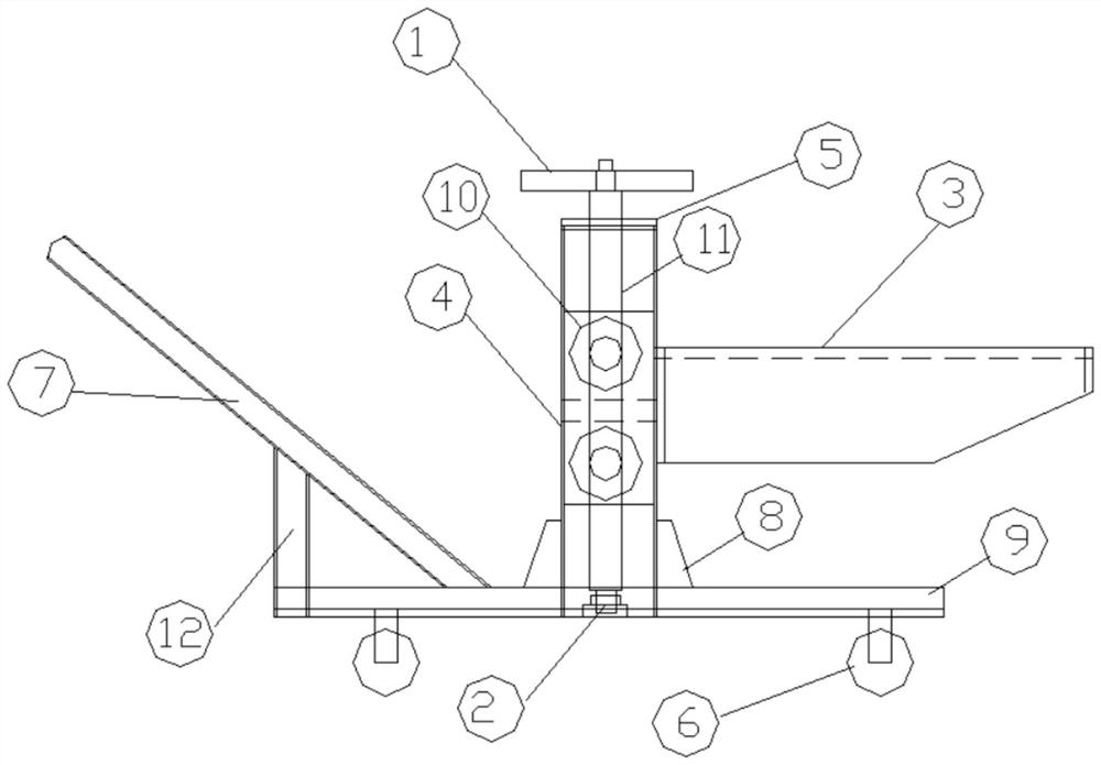
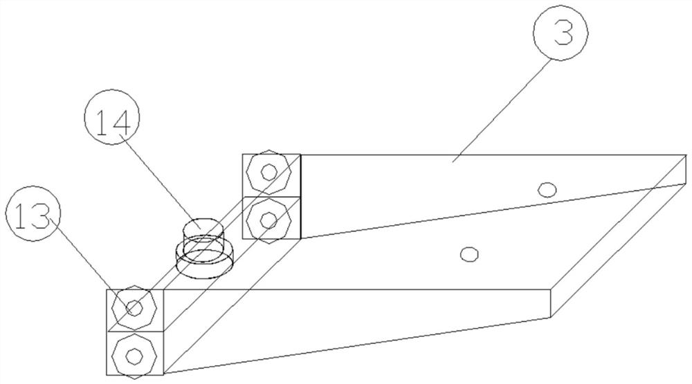
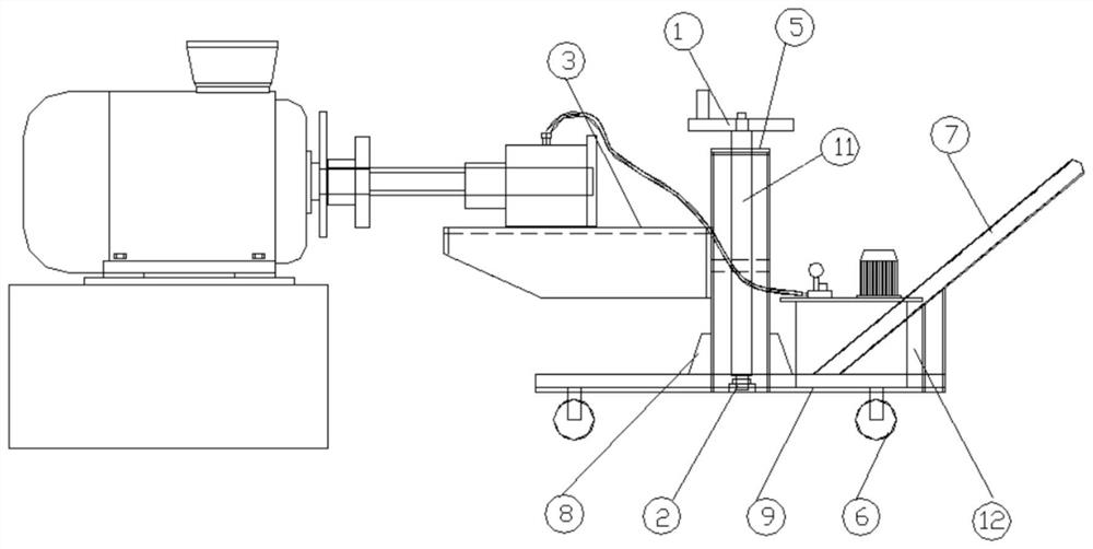
  • Click disassembling trolley with height-adjustable workbench through screw
  • Click disassembling trolley with height-adjustable workbench through screw
  • Click disassembling trolley with height-adjustable workbench through screw

Examples


Embodiment Construction

[0018] The following will clearly and completely describe the technical solutions in the embodiments of the present invention with reference to the accompanying drawings in the embodiments of the present invention. Obviously, the described embodiments are only some, not all, embodiments of the present invention. Based on the embodiments of the present invention, all other embodiments obtained by persons of ordinary skill in the art without making creative efforts belong to the protection scope of the present invention.

[0019] see Figure 1-3 , a click dismantling trolley whose height can be adjusted by a screw on the workbench, including a workbench 3, two reserved slots are drilled on the plane, and are evenly distributed side by side so that the hydraulic jack can be fixed by rope binding or bolts, so that the hydraulic jack can be stably Placed on the workbench 3, a hydraulic jack is placed at the front end of the workbench 3, a pair of square plates are welded and drille...


PUM


Abstract

The invention discloses a click disassembling trolley with a height-adjustable workbench through a screw, and relates to the technical field of ship manufacturing equipment. The click disassembling trolley comprises a trolley bottom plate, wherein universal hand-push wheels are arranged at the bottom end of the trolley bottom plate, and a supporting rod is connected to one side of the top end of the trolley bottom plate; and a hand-push rod is connected to the top end of the supporting rod, a door-type frame is arranged at the top end of the trolley bottom plate, channel steel is arranged on the two sides of the interior of the door-type frame, and the screw is connected to the interior of the door-type frame. According to the click disassembling trolley, a hand wheel, bearings, the workbench, the channel steel, the door-type frame, the universal hand-push wheels, the hand-push rod, triangular plate reinforcing ribs, the trolley bottom plate, a first bearing set, the screw, the supporting rod, a second bearing set and a nut are arranged, so that the characteristics of being simple in structure, simple to machine and manufacture, low in manufacturing cost, convenient to operate andthe like are achieved, the labor intensity of operators is obviously reduced, the working efficiency and the construction quality are improved, and the cost for installing a propeller is further reduced.

Description

technical field [0001] The invention relates to the technical field of shipbuilding equipment, in particular to a clicking and dismantling trolley whose height of the working table can be adjusted by a screw. Background technique [0002] Nowadays, with the increase in the number of ship repairs and the increase in repair tonnage, motor repairs are becoming more and more frequent, and the size of the motor is also increasing. The motor is closely related to many important parts such as ventilation, pumps, and generators on the ship. The efficiency and quality of its dismantling work are directly related to the delivery process of ship repairs. In the repair process of larger motors, the hydraulic coupling puller device is required to disassemble the motor coupling; when the puller device is working, it is necessary to use the hydraulic coupling The jack, puller device and the coupling on the motor are fixed at the same level, and the coupling is pulled out by hydraulic press...

Claims


Application Information

Patent Timeline
Patent Type & Authority Applications(China)
IPC IPC(8): B25B27/02
CPCB25B27/026
Inventor 卢宇杨志辉卢纪文税镭陈武华
Owner 中国船舶集团广西造船有限公司
Learn More