
Full-automatic cement flue machine production line device

A flue machine and production line technology, used in ceramic molding machines, ceramic molding workshops, manufacturing tools, etc., can solve the problems of time-consuming and labor-intensive specifications, low efficiency, increase labor costs and labor intensity, etc., to reduce the degree of scrap, Improve work efficiency and reduce labor costs

Pending Publication Date: 2021-02-19
宁波市镇海均胜机械有限公司
View PDF0 Cites 0 Cited by
  • Summary
  • Abstract
  • Description
  • Claims
  • Application Information

AI Technical Summary

Problems solved by technology

[0002] Cement flues are widely used in the construction industry, especially in the smoke exhaust ducts of residential buildings. Most of the cement flues produced in the past are made by hand. During construction, they are either built with bricks or poured with steel bars and concrete. The above method is not only time-consuming and laborious, but also has inconsistent specifications and sizes, which affects the overall quality of the built house, and is not efficient. The use of molds, artificial cement smoke exhaust, and air ducts cannot meet the requirements of the Ministry of Construction. In particular, the two important indicators of the cement flue products, the flexible impact resistance and the fire resistance limit, cannot meet the standard requirements. At the same time, the produced flue wall is generally thin, loose and porous, which leads to its mechanical strength not meeting the national standard. , seriously affecting the quality of the building
[0003] The existing cement flue production is generally made manually without a corresponding production line, which is time-consuming and laborious, and at the same time increases labor costs and labor intensity

Method used


Image

  • Full-automatic cement flue machine production line device
  • Full-automatic cement flue machine production line device
  • Full-automatic cement flue machine production line device

Examples


Embodiment

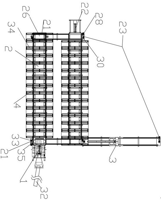
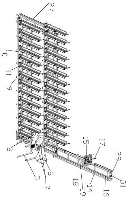
[0023] Such as Figure 1-4As shown, the technical solution adopted by the present invention to solve the above technical problems is: the technical solution adopted by the present invention to solve the above technical problems is: a fully automatic cement flue machine production line device, including automatic feeder mixer grouting mechanism assembly 1 , flue mold assembly 2, demoulding and clamping mechanism assembly 3, vibration mechanism assembly 20, transition circulation track 4, transition traction mechanism assembly 21, mold pushing cylinder 22 and motor assembly 23, said flue mold assembly 2 is arranged on the mold On the group circulation track 4, the automatic feeder mixer grouting mechanism assembly 1 is arranged above the transition circulation track 4, the demoulding and clamping mechanism component 3 is connected with the transition circulation track 4, and the demoulding and clamping mechanism 3 Located on the side of the grouting mechanism assembly 1 of the a...


PUM


Abstract

The invention discloses a full-automatic cement flue machine production line device. The full-automatic cement flue machine production line device comprises an automatic feeder, stirrer and grouting mechanism assembly, a flue mold assembly, a demolding and mold locking mechanism assembly, a vibration mechanism assembly, a transition circulation track, a transition traction mechanism assembly, a mold pushing oil cylinder assembly and a motor assembly, wherein the automatic feeder, stirrer and grouting mechanism assembly is located above the flue mold assembly, the vibration mechanism assembly is arranged below the module transition circulation track, the transition traction mechanism assembly and the mold pushing oil cylinder assembly are arranged at the two ends of the module transition circulation track, and the motor assembly is arranged on the module transition traction assembly, the demolding and mold locking mechanism assembly and the automatic feeder, stirrer and grouting mechanism assembly. The operation mode of the assembly line has the advantages that the labor cost can be effectively reduced, the working efficiency is improved, unnecessary losses are avoided, meanwhile, the labor fatigue is reduced, and the yield in unit time is high.

Description

technical field [0001] The invention relates to a fully automatic cement flue machine production line device. Background technique [0002] Cement flues are widely used in the construction industry, especially in the smoke exhaust ducts of residential buildings. Most of the cement flues produced in the past are made by hand. During construction, they are either built with bricks or poured with steel bars and concrete. The above method is not only time-consuming and laborious, but also has inconsistent specifications and sizes, which affects the overall quality of the built house, and is not efficient. The use of molds, artificial cement smoke exhaust, and air ducts cannot meet the requirements of the Ministry of Construction. In particular, the two important indicators of the cement flue products, the flexible impact resistance and the fire resistance limit, cannot meet the standard requirements. At the same time, the produced flue wall is generally thin, loose and porous, w...

Claims


Application Information

Patent Timeline
Patent Type & Authority Applications(China)
IPC IPC(8): B28B15/00
CPCB28B15/00
Inventor 潘存均
Owner 宁波市镇海均胜机械有限公司
Learn More