Dyeing device for mouth part of porcelain cup
A mouth and color printing technology, applied in printing, printing presses, rotary printing presses, etc., can solve the problems of uneven artificial coloring and long production cycle, and achieve the effect of reducing labor costs, reducing workload, and being easy to use.
- Summary
- Abstract
- Description
- Claims
- Application Information
AI Technical Summary
Problems solved by technology
Method used
Image
Examples
Embodiment 1
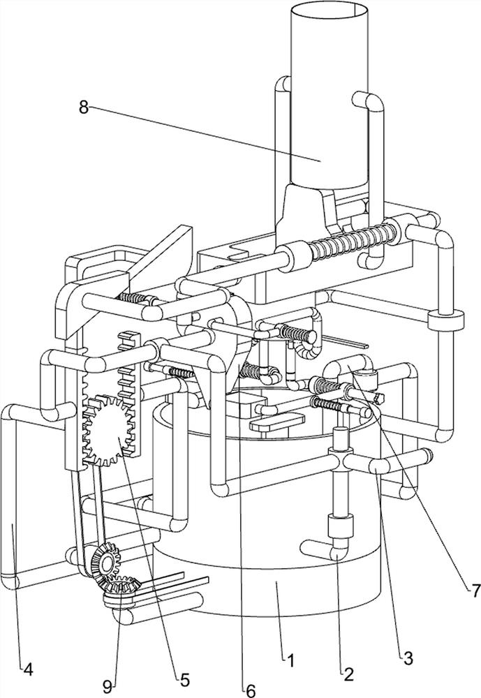
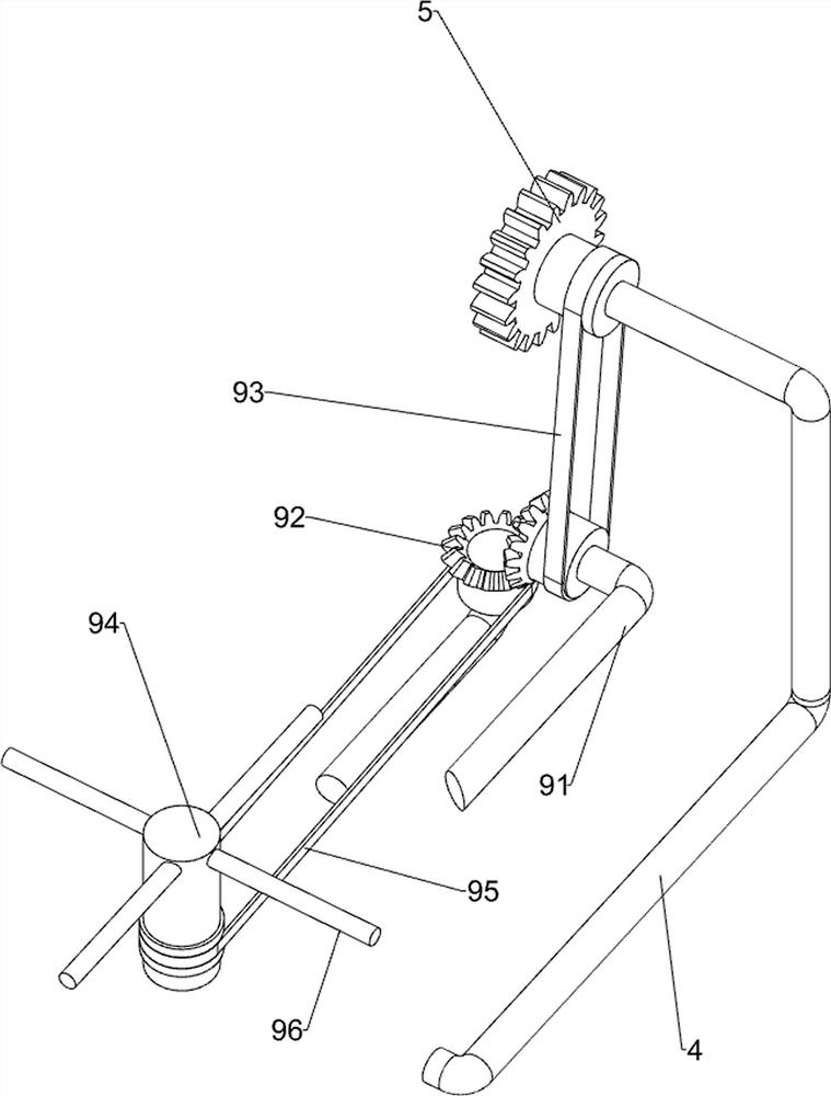
[0024] A color printing device at the mouth of a porcelain cup, such as figure 1 , figure 2 , image 3 and Figure 4 As shown, it includes a supporting paint frame 1, a first fixed rod 2, a handle 3, a second fixed rod 4, a spur gear 5, a press-down feeding mechanism 6 and a discharge smearing mechanism 7, and the upper front side of the supporting paint frame 1 is provided with The first fixed rod 2, the sliding type on the first fixed rod 2 is provided with the handle 3, the rear side of the supporting paint frame 1 is provided with the second fixed rod 4, and the front side of the second fixed rod 4 is rotatably provided with a spur gear 5, supporting the paint The frame 1 is provided with a push-down feeding mechanism 6, and the supporting paint frame 1 is provided with a discharging and smearing mechanism 7.
[0025] First, the paint is poured into the supporting paint frame 1, and then the porcelain cup that needs to be printed on the mouth is placed on the push-down...
Embodiment 2
[0027] On the basis of Example 1, such as figure 1 , figure 2 , image 3 and Figure 4 As shown, the pressing feeding mechanism 6 includes a first sliding sleeve 61, a first connecting rod 62, a trapezoidal block 63, a second sliding sleeve 64, a driving rod 65, a third fixed rod 66, a third sliding sleeve 67, and a driving block. 68. The second connecting rod 69, the first spring 610, the first rack 611, the third spring 614, the blocking rod 615, the fourth fixing rod 612 and the feeding pipe 613, and the supporting paint frame 1 is symmetrically provided with a third fixed Rod 66, on the third fixed rod 66, the third sliding sleeve 67 is provided slidingly, and the third sliding sleeve 67 is equipped with a third spring 614, the outside of the third spring 614 is connected with the third fixed rod 66, and the third sliding sleeve The cover 67 is provided with a driving block 68, the handle 3 is provided with a first sliding sleeve 61, the first sliding sleeve 61 is prov...
Embodiment 3
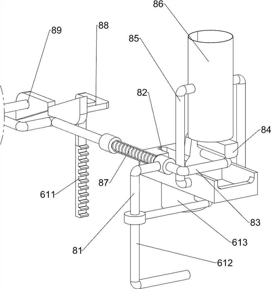
[0032] On the basis of Example 2, such as Figure 5 and Figure 6 As shown, an automatic feeding mechanism 8 is also included, and the downward pressure feeding mechanism 6 is provided with an automatic feeding mechanism 8. The automatic feeding mechanism 8 includes a fifth sliding sleeve 81, a discharge frame 82, a fourth connecting rod 83, a pushing block 84, the fifth fixed rod 85, the material storage frame 86, the second spring 87, the fifth connecting rod 88 and the oblique block 89, the fourth fixed rod 612 is provided with the fifth sliding sleeve 81, and the fifth sliding sleeve 81 slides The formula is provided with a fourth connecting rod 83, the fourth connecting rod 83 is covered with a second spring 87, the right side of the second spring 87 is connected with the fifth sliding sleeve 81, and the left side of the fourth connecting rod 83 is provided with an oblique block 89, The discharge pipe 613 is provided with a discharge frame 82, the fourth connecting rod 8...
PUM
 Abstract
Description
Claims
Application Information
 - R&D
- Intellectual Property
- Life Sciences
- Materials
- Tech Scout
- Unparalleled Data Quality
- Higher Quality Content
- 60% Fewer Hallucinations
Browse by: Latest US Patents, China's latest patents, Technical Efficacy Thesaurus, Application Domain, Technology Topic, Popular Technical Reports.
© 2025 PatSnap. All rights reserved.Legal|Privacy policy|Modern Slavery Act Transparency Statement|Sitemap|About US| Contact US: help@patsnap.com


