Curved pipe type vortex reduction system with high-radius outlet

A radius and curved tube technology, applied in the field of drag reduction, can solve problems such as air flow viscous dissipation, and achieve the effects of reducing flow resistance, reducing dissipation, and reducing vibration

Pending Publication Date: 2021-02-19
BEIHANG UNIV
View PDF6 Cites 6 Cited by
  • Summary
  • Abstract
  • Description
  • Claims
  • Application Information

AI Technical Summary

Problems solved by technology

However, the straight tube type vortex reducer will cause the contraction and expansion of the airflow channel at its inlet and outlet, causing the viscous dissipation of the airflow, and doing negative work on the airflow.

Method used


Image

  • Curved pipe type vortex reduction system with high-radius outlet
  • Curved pipe type vortex reduction system with high-radius outlet
  • Curved pipe type vortex reduction system with high-radius outlet

Examples


Embodiment Construction

[0034] The inventors found that the pressure loss in the disc cavity is mainly composed of three parts: the free vortex produced by the gas flowing out of the drum hole from the high radius to the low radius in the disc cavity hinders the radial flow of the air flow; The pressure loss generated inside the tube; when the airflow flows out from the low-radius vortex reducing nozzle, it has a high velocity, and after impacting the rotating shaft, the flow direction changes from radial to axial, resulting in a large pressure loss. Based on this, the present application was developed.

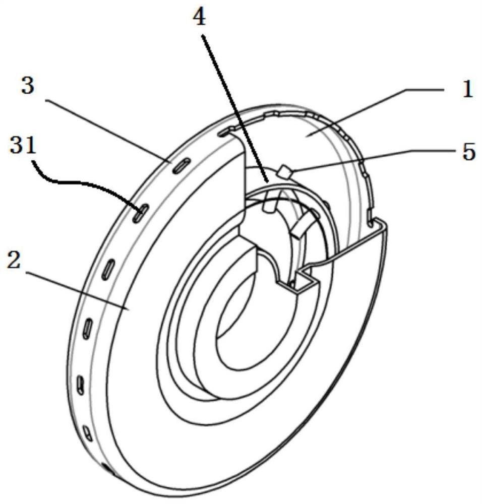
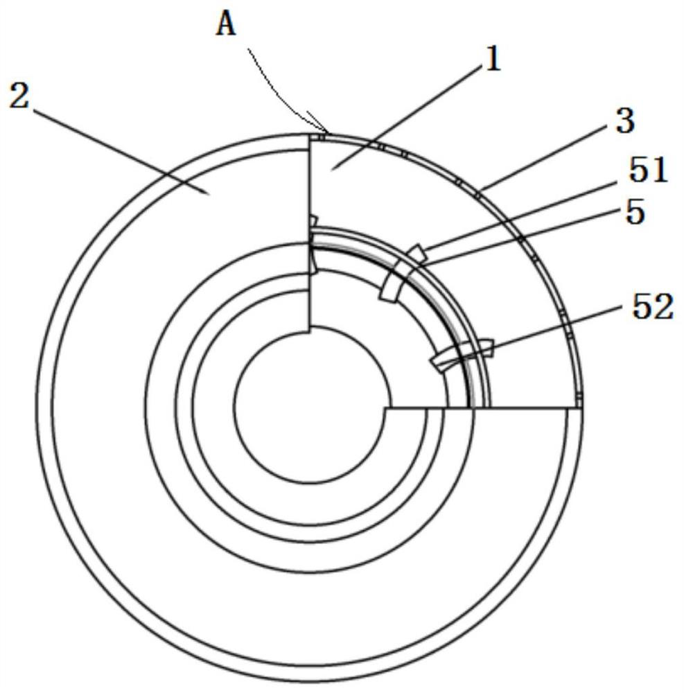
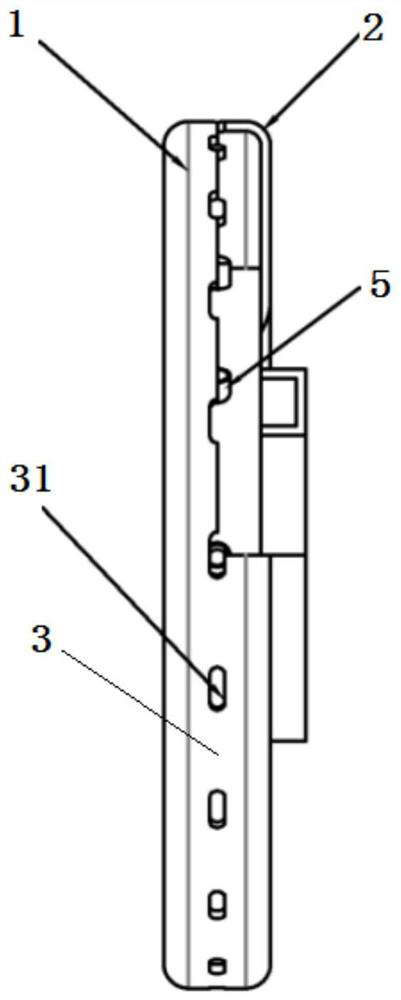
[0035] figure 1 It is a schematic perspective view of a curved tube type vortex reduction system with a high radius outlet according to an embodiment of the present application. figure 2 yes figure 1 Schematic front view of curved tube vortex reduction system with high radius outlet shown. image 3 yes figure 1 Schematic top view of curved tube vortex reduction system with high radius outlet sh...


PUM


Abstract

The invention discloses a curved pipe type vortex reduction system with a high-radius outlet, and relates to aero-engines. The curved pipe type vortex reduction system comprises a chuck and a plurality of curved vortex reducing pipes. A plurality of curved vortex reducing pipes are uniformly arranged in the circumferential direction of the chuck and are coaxial with compressor discs on the two sides, the curved vortex reducing pipes are the same in structure and mounting radius, each curved vortex reducing pipe is provided with a curved vortex reducing pipe inlet and a curved vortex reducing pipe outlet, and the inlet of each curved vortex reducing pipe faces the airflow direction, so that pressure loss caused when the airflow is separated at the inlet of the vortex reducing pipe to form avortex is reduced, and the outlet position of each curved vortex reducing pipe rotates reversely, so that the circumferential speed of the airflow is limited, the development of free vortexes is inhibited, and the flow obstruction is reduced. Therefore, according to the curved pipe type vortex reduction system with the high-radius outlet, aerodynamic characteristics are fully considered, free vortex development in the radial inflow disc cavity is restrained, meanwhile, dissipation, caused by turning, of airflow is reduced, and pressure loss in the system is reduced.

Description

technical field [0001] The present application relates to the technical field of drag reduction in the bleed air section of a compressor of an aero-engine secondary air system, and in particular to a curved-tube vortex reduction system for high-radius outlets of aero-engines. Background technique [0002] Advanced aero-engines pursue a higher thrust-to-weight ratio, higher thermal efficiency, longer service life and higher reliability, so it is necessary to continuously increase the boost ratio of the compressor and increase the temperature before the turbine. The temperature in front of the turbine of the aero-engine has been increasing, and the temperature has exceeded the heat resistance limit of the existing turbine materials. In addition, the higher temperature will cause the thermal creep of the turbine to increase and reduce its life. Therefore, it is necessary to cool the temperature before the turbine to a lower range. [0003] At present, the cooling method used i...

Claims


Application Information

Patent Timeline
Patent Type & Authority Applications(China)
IPC IPC(8): F02C3/04F01D9/04F04D29/66F04D29/40
CPCF02C3/04F01D9/04F04D29/667F04D29/403
Inventor 罗翔何建白阳
Owner BEIHANG UNIV
Why Eureka
Try Eureka