Central flue air volume control method and system

An air volume control system and air volume control technology, which are applied in heating methods, oil fume removal, lighting and heating equipment, etc., can solve problems such as inability to distribute air volume on floors, and achieve the effect of eliminating smoke.

Active Publication Date: 2021-02-19
VATTI CORP LTD
View PDF15 Cites 3 Cited by
  • Summary
  • Abstract
  • Description
  • Claims
  • Application Information

AI Technical Summary

Problems solved by technology

[0004] In order to solve the problem that the current central flue air volume control system evenly distributes the air volume of each floor in the process of not being able to distribute the floor air volume according to the actual use of users, the present invention provides a central flue air volume control method

Method used


Image

  • Central flue air volume control method and system
  • Central flue air volume control method and system
  • Central flue air volume control method and system

Examples


Embodiment 1

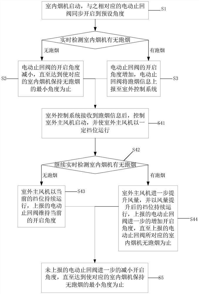
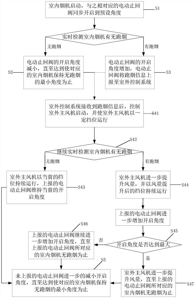
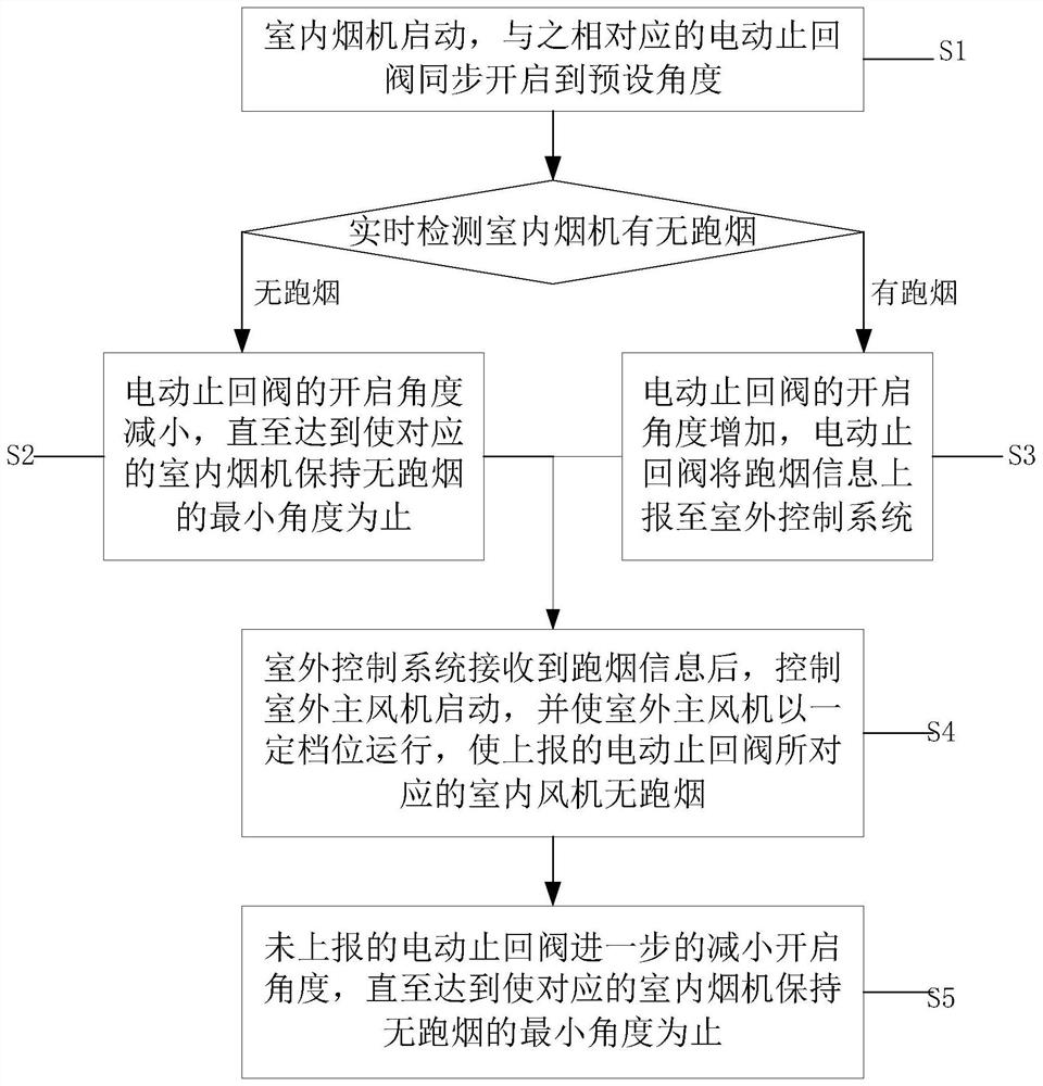
[0049] Such as figure 1 As shown, the present embodiment provides a central flue air volume control method, the method includes the following steps:

[0050] S1. Start the indoor hood, and the corresponding electric check valve is synchronously opened to the preset angle to detect in real time whether there is any smoke from the indoor hood; if there is no smoke, go to S2; if there is smoke, go to S3 ;

[0051] S2. The opening angle of the electric check valve is reduced until it reaches the minimum angle at which the corresponding indoor range hood remains free of smoke;

[0052] S3. The opening angle of the electric check valve is increased, and the electric check valve will report the smoke information to the outdoor control system;

[0053] S4. After receiving the smoke information, the outdoor control system controls the outdoor main fan to start, and makes the outdoor main fan run at a certain gear, so that the indoor hood corresponding to the reported electric check v...

Embodiment 2

[0074] Such as Figure 4 and Figure 5 As shown, this embodiment provides a central flue air volume control system, including an indoor smoke machine 1 installed on each floor, an outdoor control system, a smoke detection component 3 and an electric check valve 5;

[0075] Each indoor smoke machine 1 communicates with the public flue 4 through its own smoke pipe 11, and an electric check valve 5 is installed on each smoke pipe 11; the smoke detector assembly 3 is connected with each indoor smoke machine 1 for detection Whether the indoor smoke machine 1 runs out of smoke; the outdoor control system includes the outdoor main fan 2 installed at the air outlet of the public flue 4, and the outdoor control system is connected with each electric check valve 5 for communication according to the received electric check valve. 5 to control the opening, closing, and gear adjustment of the outdoor main fan 2 by sending out smoke information.

[0076] Because the smoke detector compone...


PUM


Abstract

The invention belongs to the technical field of central flue systems, and discloses a central flue air volume control method and system. The method comprises the steps that indoor range hoods are started, electric check valves are synchronously opened to a preset angle, and whether smoke leaks from the indoor range hoods or not is detected in real time; if the smoke does not leak, the opening angles of the electric check valves are reduced until the minimum angle at which corresponding indoor range hoods are free of smoke leakage is reached; otherwise, the opening angles of the electric checkvalves are increased and the electric check valves are reported to an outdoor control system; after the outdoor control system receives smoke leakage information, an outdoor main fan is controlled tobe started, the outdoor main fan is made to operate at a certain gear, and the indoor range hoods corresponding to the reported electric check valves are made to be free of smoke leakage; and the opening angles of electric check valves which are not reported are further reduced until the minimum angle at which the corresponding indoor range hoods are free of smoke leakage is reached. By means of the control method, air volume distribution of all floors can be achieved according to the actual situation.

Description

technical field [0001] The invention belongs to the technical field of central flue systems, and in particular relates to a central flue air volume control method and system. Background technique [0002] In recent years, a concept of "concentrated fume exhaust system for building public flue" has emerged as the times require, which generates additional power through fans placed at the top of the public flue, and cooperates with the indoor range hoods of each household to achieve uniform air volume on each floor Distribution, so as to achieve the purpose of smooth smoke exhaust and low noise use. [0003] However, this method of evenly distributing the air volume of each floor is a relatively blind control method, and the air volume allocated to each household is not high. In addition, in the actual use process of users, each household's demand for air volume at the same time period is inconsistent. , the method of evenly distributing the air volume of each floor cannot be ...

Claims


Application Information

Patent Timeline
Patent Type & Authority Applications(China)
IPC IPC(8): F24C15/20
CPCF24C15/2021Y02B30/70
Inventor 王智捷余丹阳彭锦宇张辉珉李永波姚家前潘叶江
Owner VATTI CORP LTD
Why Eureka
Try Eureka