
Electric cabinet electric leakage alarm device

A technology for alarm devices and electrical cabinets, which is applied to alarms, measuring devices, and housings of measuring devices. It can solve the problems of cable shedding, troublesome installation, and time-consuming and labor-intensive disassembly, and achieves time-saving and labor-saving installation and disassembly. The effect of improving work efficiency

Pending Publication Date: 2021-02-19
无锡嘉威电气智能科技有限公司
View PDF10 Cites 4 Cited by
  • Summary
  • Abstract
  • Description
  • Claims
  • Application Information

AI Technical Summary

Problems solved by technology

[0003] Existing electrical cabinets are often equipped with leakage detectors for leakage detection and alarms during leakage, but the existing leakage detectors are fixed with bolts during installation, which is not only cumbersome to install, but also time-consuming and laborious to disassemble; and When the existing leakage detector is connected with the cable in the electric cabinet, the cable is connected to the terminal of the leakage detector and the mechanism is fixed, and the cable is easy to fall off from the terminal, which makes it impossible to perform leakage detection; and the existing The warning light and buzzer of the electric cabinet leakage alarm device are exposed outside, and dust is easy to fall on the surface, which will affect the effect of the alarm

Method used


Image

  • Electric cabinet electric leakage alarm device
  • Electric cabinet electric leakage alarm device
  • Electric cabinet electric leakage alarm device

Examples


Embodiment Construction

[0026] The following will clearly and completely describe the technical solutions in the embodiments of the present invention with reference to the accompanying drawings in the embodiments of the present invention. Obviously, the described embodiments are only some, not all, embodiments of the present invention.

[0027] In describing the present invention, it should be understood that the terms "upper", "lower", "front", "rear", "left", "right", "top", "bottom", "inner", " The orientation or positional relationship indicated by "outside", etc. is based on the orientation or positional relationship shown in the drawings, and is only for the convenience of describing the present invention and simplifying the description, rather than indicating or implying that the referred device or element must have a specific orientation, so as to Specific orientation configurations and operations, therefore, are not to be construed as limitations on the invention.

[0028] refer to Figure ...


PUM


Abstract

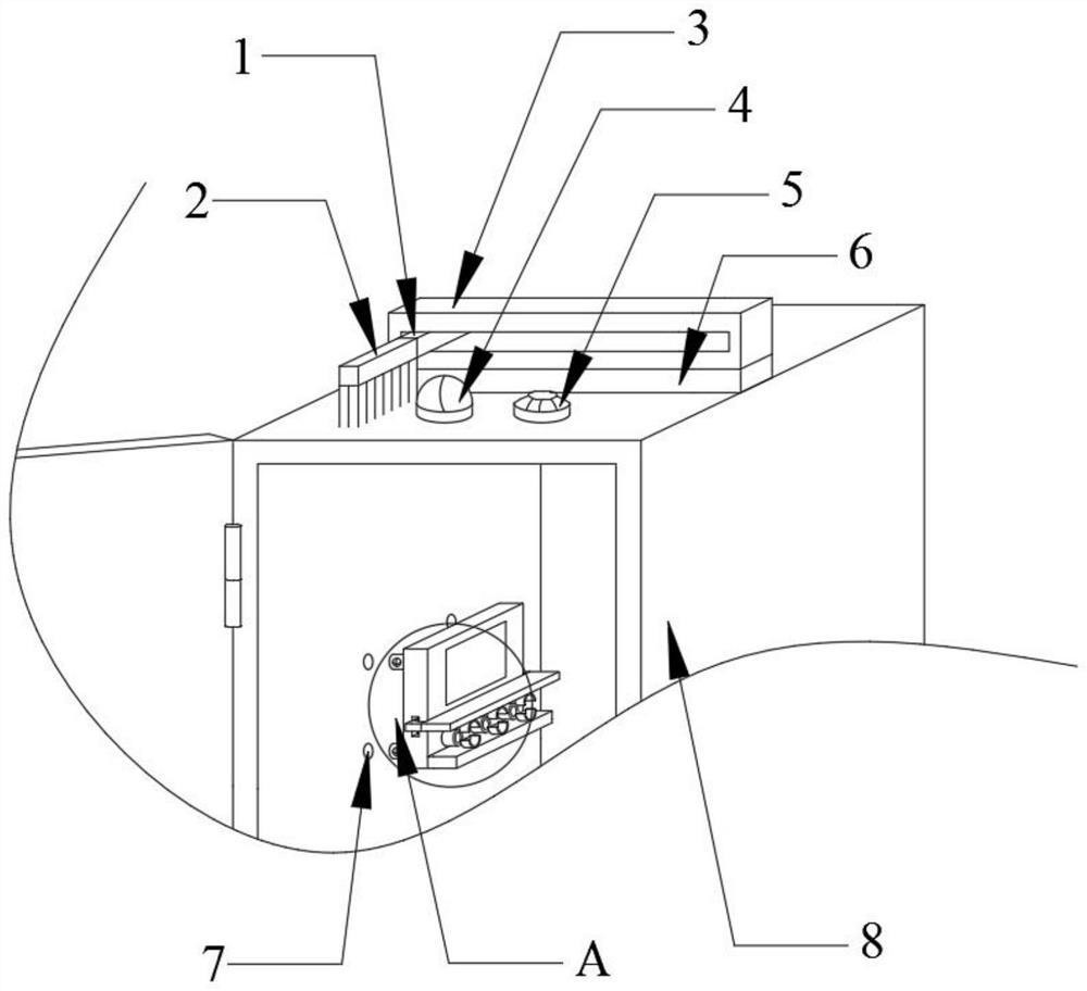
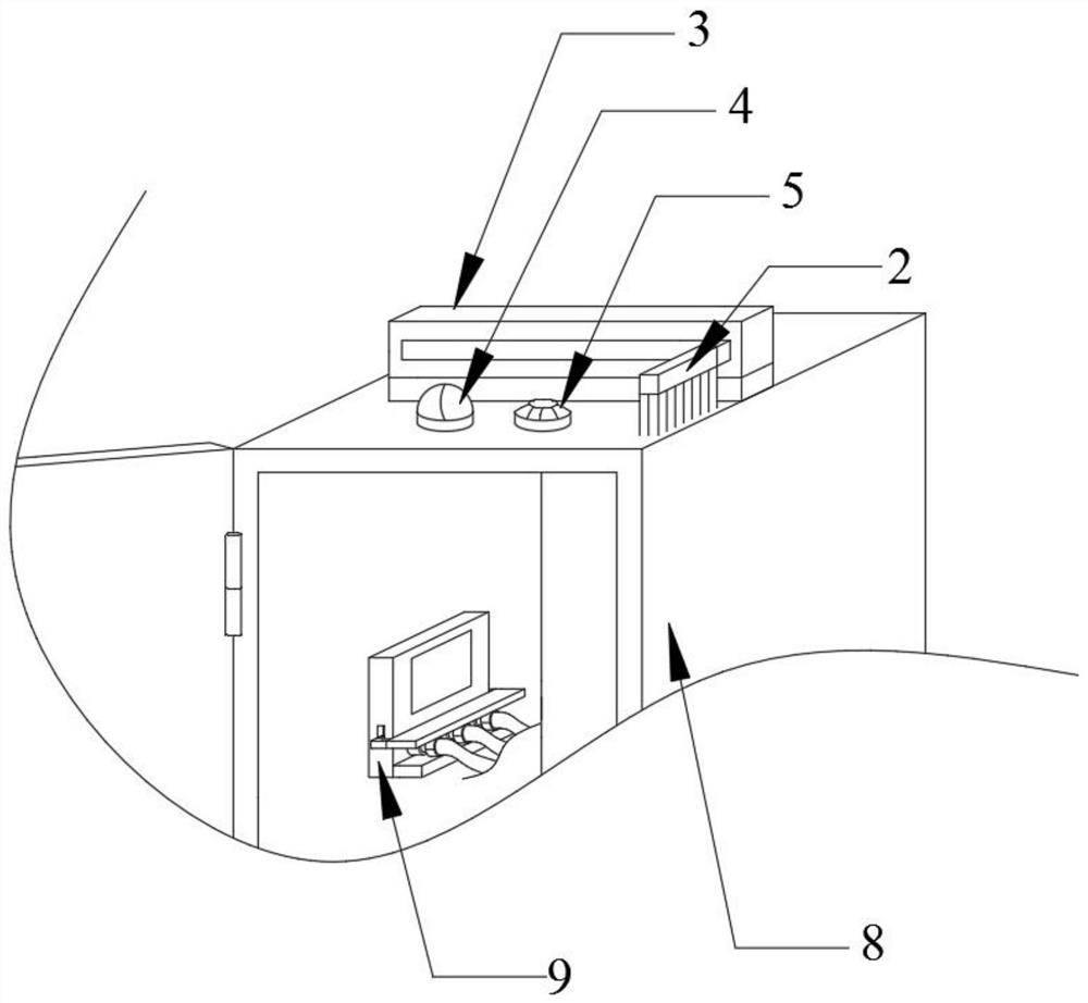
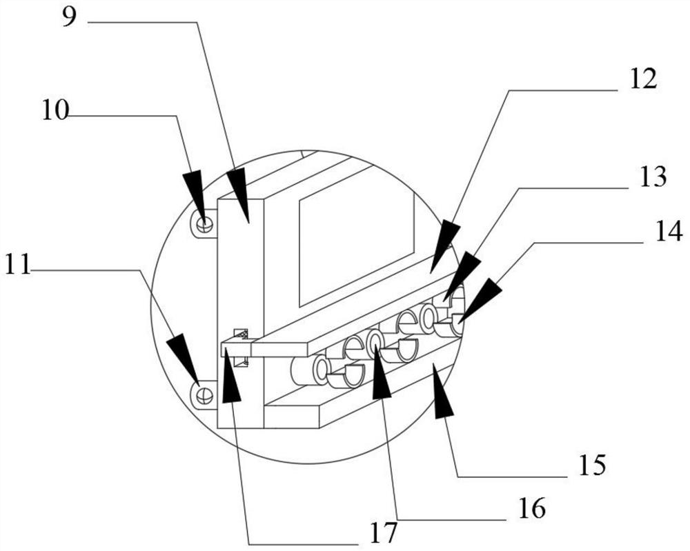
The invention belongs to the technical field of electric cabinets, particularly relates to an electric cabinet electric leakage alarm device, and provides the following scheme for solving the problemthat an electric leakage detector is inconvenient to install: the electric cabinet electric leakage alarm device comprises an electric cabinet and the electric leakage detector, a warning lamp and a buzzer are installed on one side of the top of the electric cabinet, and a dust removal mechanism is arranged in the middle of the top of the electric cabinet. A fixed plate is welded to the bottom ofone side of the electric leakage detector, a lower fixed ring is welded to the top of the fixed plate, a movable plate is arranged above the fixed plate, an upper fixed ring is welded to the bottom ofthe movable plate, L-shaped rods are welded to the two ends of the movable plate, and sliding grooves are vertically formed in the lower middle portions of the two opposite sides of the electric leakage detector. Locking mechanisms are arranged in the sliding grooves, and first inserting columns are welded to the four corners of the side face of the electric leakage detector. The electric leakagedetector is time-saving and labor-saving to mount and dismount, the working efficiency is improved, the cable is prevented from falling off from the wiring terminal, and the electric leakage detection can be carried out all the time.

Description

technical field [0001] The invention relates to the technical field of electric cabinets, in particular to an electric cabinet leakage alarm device. Background technique [0002] Electric cabinets are power distribution cabinets, which are divided into power distribution cabinets, lighting distribution cabinets, and metering cabinets. They are the final equipment of the power distribution system. The power distribution cabinet is the general name of the motor control center. The power distribution cabinet is used in the occasions where the load is relatively scattered and there are few circuits; the motor control center is used in the occasions where the load is concentrated and there are many circuits. They distribute the electric energy of a certain circuit of the upper-level power distribution equipment to the nearest load, and this level of equipment should provide protection, monitoring and control for the load. [0003] Existing electrical cabinets are often equipped ...

Claims


Application Information

Patent Timeline
Patent Type & Authority Applications(China)
IPC IPC(8): G01R31/52G01R31/56G01R1/04B08B1/00G08B21/18
CPCG01R31/52G01R31/56G01R1/0408G08B21/185B08B1/12
Inventor 邰士清李健姜鑫郭大聪吴正
Owner 无锡嘉威电气智能科技有限公司
Learn More