Method for realizing self-oscillation multi-carrier optical fiber light source and multi-carrier optical fiber light source system

A fiber optic light source, multi-carrier technology, applied in electromagnetic wave transmission systems, transmission systems, electromagnetic transmitters and other directions, can solve the problem of limiting the coverage of the output spectrum flatness carrier, and achieve low phase noise, flat power, and large coverage. Effect

Active Publication Date: 2021-02-19
TIANJIN UNIV
View PDF4 Cites 0 Cited by
  • Summary
  • Abstract
  • Description
  • Claims
  • Application Information

AI Technical Summary

Problems solved by technology

However, the analysis of its system structure shows that the multi-carrier generation mechanism in the multi-carrier fiber optic light source based on the optoelectronic oscillator is still a single modulation with a certain modulation depth using modulators or cascaded modulators, which greatly limits its output. Optimization of spectral flatness and further expansion of carrier coverage

Method used


Image

  • Method for realizing self-oscillation multi-carrier optical fiber light source and multi-carrier optical fiber light source system
  • Method for realizing self-oscillation multi-carrier optical fiber light source and multi-carrier optical fiber light source system
  • Method for realizing self-oscillation multi-carrier optical fiber light source and multi-carrier optical fiber light source system

Examples


Embodiment Construction

[0040] The method for realizing a self-oscillating multi-carrier fiber optic light source and the multi-carrier fiber optic light source system of the present invention will be described in detail below in conjunction with the embodiments and accompanying drawings.

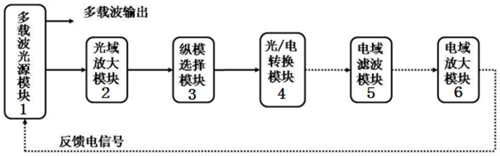
[0041] The method for realizing the self-oscillating multi-carrier fiber optic light source of the present invention, the output optical signal of the free oscillation of the multi-carrier fiber optic light source undergoes multi-stage processing in the optical domain and the electrical domain, and obtains a low-phase noise, high-intensity specific frequency electrical signal, and feeds back Back to the multi-carrier fiber optic light source, drive the multi-carrier fiber optic light source to achieve self-consistent oscillation, and realize the output of a new type of broadband self-oscillating multi-carrier optical signal.

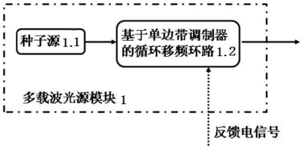
[0042] When the system is running, the multi-carrier optical fiber light source in the fr...


PUM


Abstract

The invention discloses a method for realizing a self-oscillation multi-carrier optical fiber light source and a multi-carrier optical fiber light source system. The method comprises the following steps: establishing a multi-carrier optical fiber light source based on a cyclic frequency shift loop; amplifying an optical signal output by the multi-carrier optical fiber light source in an optical domain; carrying out longitudinal mode selection on the amplified optical signal in an optical domain; converting the optical signals subjected to longitudinal mode selection into corresponding electricsignals with different frequencies; carrying out electric domain filtering on the electric signal; carrying out electric domain amplification on the filtered electric signal; feeding back the amplified electric signal to a frequency shifter in a cyclic frequency shift loop of the multi-carrier optical fiber light source, and driving the frequency shifter to control the frequency shift amount of the optical signal, so that the multi-carrier optical fiber light source outputs the optical signal with a set frequency interval, and returning one part of the optical signal to the step 2 to carry out the next cycle; and using the other part of optical signals as multi-carrier output of the whole system. The invention has the characteristics of large output signal carrier coverage, flat power, low phase noise and no need of an additional radio frequency driving source.

Description

technical field [0001] The invention relates to an optical fiber light source. In particular, it relates to a method for realizing a self-oscillating multi-carrier fiber optic light source and a multi-carrier fiber optic light source system. Background technique [0002] Multi-carrier fiber optic light source, that is, a fiber optic light source that can simultaneously output multiple carriers of different frequencies. In recent years, multi-carrier fiber optic light sources have played an important role in communication systems such as Dense Wavelength Division Multiplexing (DWDM) and Orthogonal Frequency Division Multiplexing (OFDM), optical fiber sensing, optical component testing, spectroscopy, and phased array radar. It has been widely valued and studied by researchers at home and abroad. Multi-carrier fiber optic light sources can be divided into two categories: intracavity modulation and extracavity modulation according to their generation mechanism. [0003] (1) I...

Claims


Application Information

Patent Timeline
Patent Type & Authority Applications(China)
IPC IPC(8): H04B10/54H04B10/516
CPCH04B10/54H04B10/5165
Inventor 文莱王肇颖张拢
Owner TIANJIN UNIV
Why Eureka
Try Eureka