Liquid injection device for electronic cigarette production line

A liquid injection device and electronic cigarette technology, applied in the direction of tobacco, etc., can solve the problems that affect the injection quality, cannot guarantee the uniform injection volume, and cannot control the injection volume, so as to ensure the injection quality, avoid splashing, and uniform injection volume Effect

Active Publication Date: 2021-02-23
深圳正和生物科技有限公司
View PDF11 Cites 2 Cited by
  • Summary
  • Abstract
  • Description
  • Claims
  • Application Information

AI Technical Summary

Problems solved by technology

[0003] The liquid injection device used in the existing electronic cigarette production line cannot control the injection volume for each injection syringe, resulting in the inability to ensure uniform injection volume during injection and affecting the quality of injection. At the same time, the electronic cigarette cannot be moved to the injection position intermittently. Continuous injections are not possible

Method used


Image

  • Liquid injection device for electronic cigarette production line
  • Liquid injection device for electronic cigarette production line
  • Liquid injection device for electronic cigarette production line

Examples


Embodiment 1

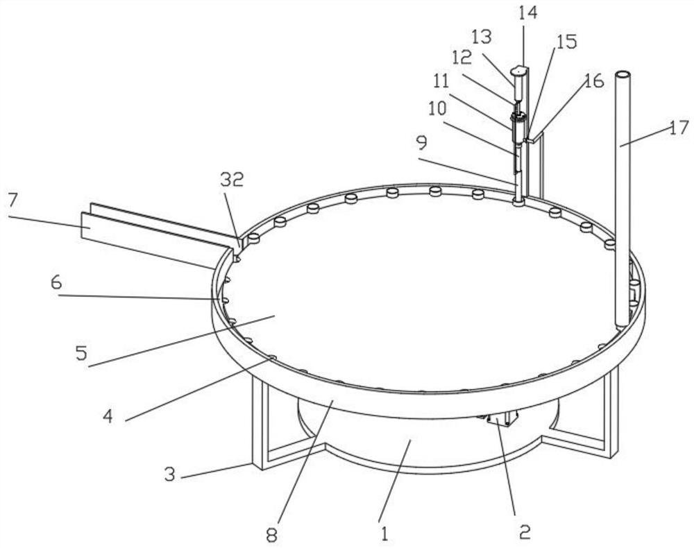
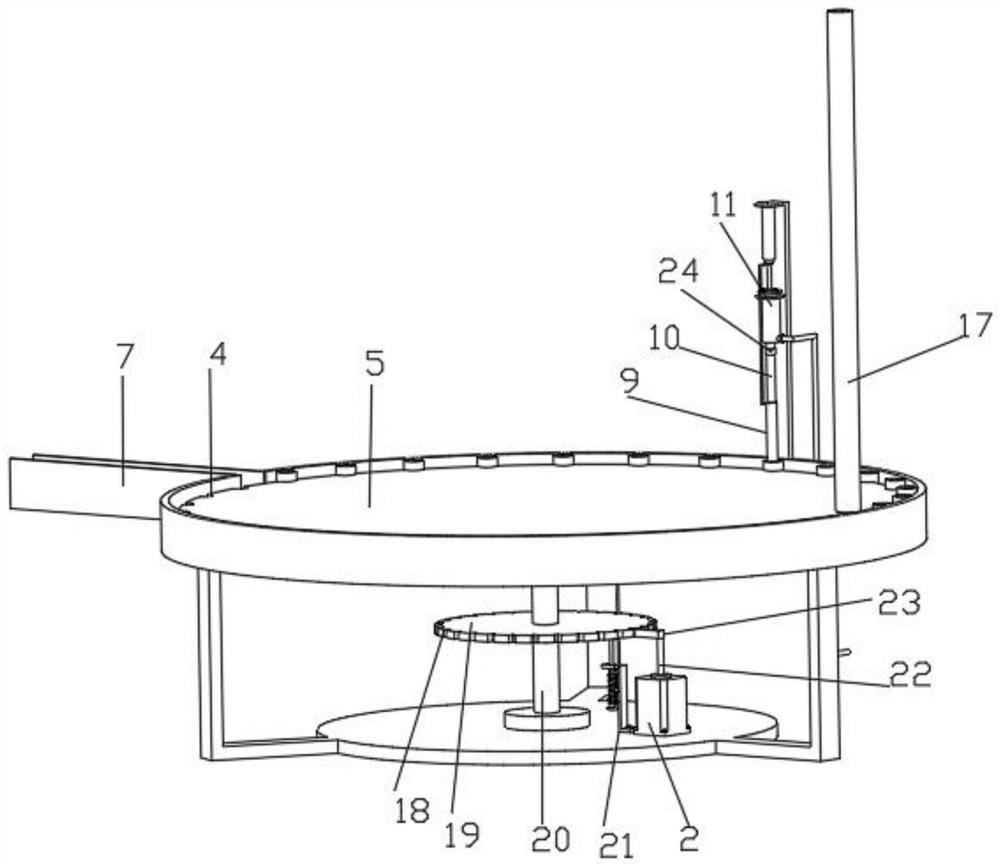
[0030] Such as figure 1 , 2 A liquid injection device for an electronic cigarette production line shown in 3, 4, and 6 includes a bottom plate 1, an intermittent pushing structure is connected to the top of the bottom plate 1, and the gap pushing structure includes a driving motor 2, an L-shaped plate 3, a semicircular groove 4, The first rotating circular plate 5, the outer ring 8, the driving groove 18, the second rotating circular plate 19, the rotating rod 20, the rotating shaft 22 and the driving block 23, the top middle end of the bottom plate 1 is rotatably connected with the rotating rod through a fixedly connected bearing 20. The output end of the driving motor 2 is fixedly connected to the rotating shaft 22, the top of the rotating shaft 22 is fixedly connected to the driving block 23, the middle end of the rotating rod 20 is guessed to be fixedly connected to the second rotating circular plate 19, and the outer surface of the second rotating circular plate 19 The e...

Embodiment 2

[0033] Embodiment 2 is a further improvement to Embodiment 1.

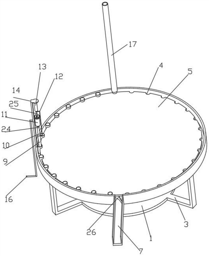
[0034] Such as figure 1 , 2 , The braking structure shown in 4 and 5 comprises Z-shaped plate 21, spring 27, disc 28, rubber plate 29 and movable bar 30, and the bottom of the top transverse part of Z-shaped plate 21 is fixedly connected with spring 27, and the bottom of spring 27 Fixedly connected with a circular plate 28, the top of the circular plate 28 is fixedly connected with a movable rod 30, the top of the movable rod 30 runs through the spring 27 and the Z-shaped plate 21 and is fixedly connected with a rubber plate 29, the top of the rubber plate 29 is connected with the second rotating circular plate The bottom of 19 fits and slides, and the bottom transverse part of the Z-shaped plate 21 is fixed on the top of the bottom plate 1 by bolts. The spring 27 of the braking structure drives the circular plate 28 to move upward, and the circular plate 28 drives the movable rod 30 to move, and the movable rod ...


PUM


Abstract

The invention discloses a liquid injection device for an electronic cigarette production line, and relates to the technical field of electronic cigarette production. The liquid injection device comprises a bottom plate, the top of the bottom plate is connected with an intermittent pushing structure, and the intermittent pushing structure comprises a driving motor, an L-shaped plate, a semicirculargroove, a first rotating circular plate, an outer ring, a driving groove, a second rotating circular plate, a rotating rod, a rotating shaft and a driving block; wherein the outer ring is fixedly provided with a feeding cylinder used for feeding electronic cigarettes in the 0-degree direction, the outer ring is provided with a discharging hole in the 270-degree direction, the outer ring is fixedly connected with a U-shaped discharging plate used for discharging in the discharging hole, and the outer ring is provided with a quantitative injection structure used for quantitative discharging inthe 360-degree direction. Quantitative injection is realized, uniformity of the injection amount is guaranteed, and the injection quality is guaranteed.

Description

technical field [0001] The invention relates to the technical field of electronic cigarette production, in particular to a liquid injection device for an electronic cigarette production line. Background technique [0002] E-cigarettes are electronic products that mimic cigarettes and have the same look, smoke, taste and feel as cigarettes. It is a product that allows users to inhale after turning nicotine, etc. into steam by means of atomization. The World Health Organization conducted research on e-cigarettes and came to a clear conclusion: e-cigarettes are harmful to public health, and it is not a means of quitting smoking. It is necessary to strengthen its control to prevent harm to young people and non-smokers. [0003] The liquid injection device used in the existing electronic cigarette production line cannot control the injection volume for each injection syringe, resulting in the inability to ensure uniform injection volume during injection and affecting the quality...

Claims


Application Information

Patent Timeline
Patent Type & Authority Applications(China)
IPC IPC(8): A24F40/48A24F40/40A24F40/10
CPCA24F40/48A24F40/40A24F40/10Y02E60/10
Inventor 胡桃莉何琛王耸霄何友根何产军
Owner 深圳正和生物科技有限公司
Why Eureka
Try Eureka