Three-shaft continuous stirring cylinder

A technology of mixing cylinder and mixing shaft, applied in the directions of dissolving, mixer, chemical instrument and method, etc., can solve the problems of short mixing time, affecting the quality of mixing and so on, and achieve the effect of good mixing quality.

Pending Publication Date: 2021-02-23
宋学忠
View PDF0 Cites 0 Cited by
  • Summary
  • Abstract
  • Description
  • Claims
  • Application Information

AI Technical Summary

Problems solved by technology

[0002] Dry powder, dry and wet mixture mixing tank equipment is the key equipment for mixing. It is mainly used to mix sand and gravel aggregates, powder, liquid and other materials into mixtures. This process has been going on for nearly a hundred years. The traditional mixture mixing tank is equipped with a rotatable stirring shaft in the cylinder body. There are inclined stirring blades distributed on the shaft diameter of the stirring shaft at intervals. Sand, gravel, powder Solids, liquids, etc. enter the mixing tank from the feed port, and under the rotation of the inclined blades, they are mixed and output from one end of the stirring shaft to the other end, and finally discharged from the discharge port; the mixing tank is from the most uniaxial to the parallel double shaft After nearly a hundred years, no matter single-axis or double-axis, there are always two relatively contradictory problems, the discharge speed and the uniformity of the mixture. The faster the stirring speed, the faster the discharge speed of the mixture, but in the mixing tank The shorter the mixing time, which affects the quality of mixing and mixing, for this reason, there are further requirements for the output speed of the mixed material and the quality of mixing and mixing. To adapt to changes and meet further challenges, to solve this contradiction is what we need now. Urgent technical problems to be solved

Method used


Image

  • Three-shaft continuous stirring cylinder
  • Three-shaft continuous stirring cylinder
  • Three-shaft continuous stirring cylinder

Examples


Embodiment Construction

[0015] Specific embodiments of the present invention will be further described in detail below in conjunction with the accompanying drawings.

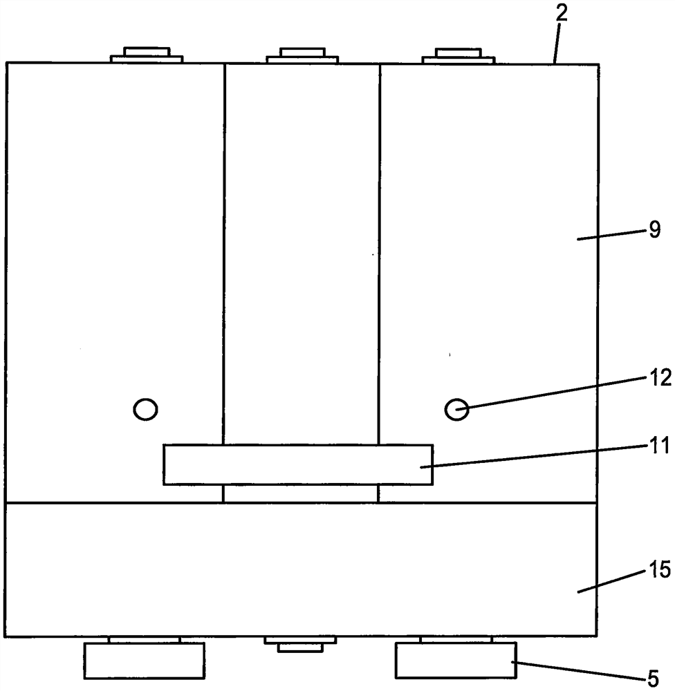
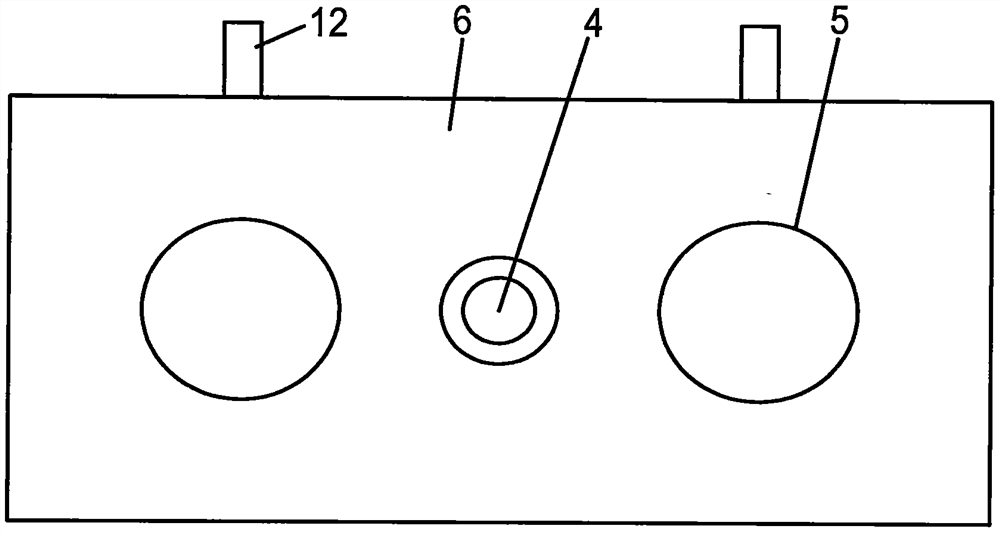
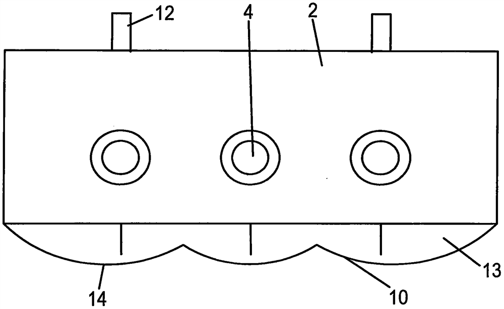
[0016] Such as Figure 1-Figure 4 As shown, the three-axis continuous mixing tank involved in the present invention includes a middle support plate 1, a rear end support plate 2, a mixing tank side wall 3, a stirring shaft 4 and a driving mechanism 5, and also includes a front support plate 6, a driving gear 7, Stirring blade 8, mixing tank upper cover plate 9 and mixing tank lower cover plate 10, the two sides of the front support plate 6, the middle support plate 1 and the rear end support plate 2 are respectively connected with the corresponding mixing tank side wall 3 and fixed as It forms a Japanese-shaped frame in one piece, and the three stirring shafts 4 are evenly arranged and respectively hinged on the front support plate 6, the middle support plate 1 and the rear end support plate 2. On the stirring shaft 4 between the supp...


PUM


Abstract

The invention relates to a three-shaft continuous stirring cylinder, which comprises a middle supporting plate, a rear end supporting plate, stirring cylinder side walls, stirring shafts and driving mechanisms, and further comprises a front end supporting plate, driving gears, stirring blades, a stirring cylinder upper cover plate and a stirring cylinder lower cover plate, both sides of the frontend supporting plate, the middle supporting plate and the rear end supporting plate are respectively connected and fixed with the corresponding side walls of the stirring cylinder to form a frame shaped like a Chinese character "ri", and the three stirring shafts are uniformly arranged and respectively hinged to the front end supporting plate, the middle supporting plate and the rear end supporting plate; according to the technical scheme, the stirring shafts on the two sides and the two sides of the stirring shaft located in the middle form two meshing areas, the mixing space is multiplied, the middle stirring shaft and the stirring shafts on the two sides are opposite in rotating direction, and the stirring cylinder upper cover plate and the stirring cylinder lower cover plate are arranged to be matched with the rotating radius of stirring blades on the stirring shafts. Therefore, the efficient mixing and kneading effect is further achieved, and the stirring cylinder not only has theside-by-side double-shaft mixture discharging speed, but also has better sufficient stirring and mixing quality.

Description

technical field [0001] The invention relates to a mixing material mixing device, in particular to a three-axis continuous mixing cylinder. Background technique [0002] Dry powder, dry and wet mixture mixing tank equipment is the key equipment for mixing. It is mainly used to mix sand and gravel aggregates, powder, liquid and other materials into mixtures. This process has been going on for nearly a hundred years. The traditional mixture mixing tank is equipped with a rotatable stirring shaft in the cylinder body. There are inclined stirring blades distributed on the shaft diameter of the stirring shaft at intervals. Sand, gravel, powder Solids, liquids, etc. enter the mixing tank from the feed port, and under the rotation of the inclined blades, they are mixed and output from one end of the stirring shaft to the other end, and finally discharged from the discharge port; the mixing tank is from the most uniaxial to the parallel double shaft After nearly a hundred years, no ...

Claims


Application Information

Patent Timeline
Patent Type & Authority Applications(China)
IPC IPC(8): B01F13/10
CPCB01F33/833B01F33/836
Inventor 宋学忠
Owner 宋学忠
Why Eureka
Try Eureka