Mixing assembly

a technology of mixing assembly and mixing chamber, which is applied in the direction of mechanical equipment, machines/engines, transportation and packaging, etc., can solve the problems of inconsistent detonation characteristics of air-gas mixture, sub-optimal detonation of air-gas and distillate mixture, etc., and achieve the effect of increasing turbulence and increasing chaotic mixing characteristics

Inactive Publication Date: 2016-07-07
GREEN JASON E
View PDF5 Cites 11 Cited by
  • Summary
  • Abstract
  • Description
  • Claims
  • Application Information

AI Technical Summary

Benefits of technology

[0014]In yet further embodiments the present invention may also include turbulating elements disposed within the housing, and especially downstream of the injector body outlet. The turbulating elements may comprise any of a variety of shapes configured to further disrupt the flow of the fluids thereby increasing turbulence and accordingly increasing the chaotic mixing characteristics of the present invention.

Problems solved by technology

However, poor mixing of the intake air and gaseous fuel can lead to sub-optimal detonation of the air-gas and distillate mixture.
For example, poor mixing can lead to a non-homogenous air-gas mixture, whereby certain regions can have varying concentrations of gaseous fluid, thereby leading to inconsistent detonation characteristics of the air-gas mixture.

Method used


Image

  • Mixing assembly
  • Mixing assembly
  • Mixing assembly

Examples


Embodiment Construction

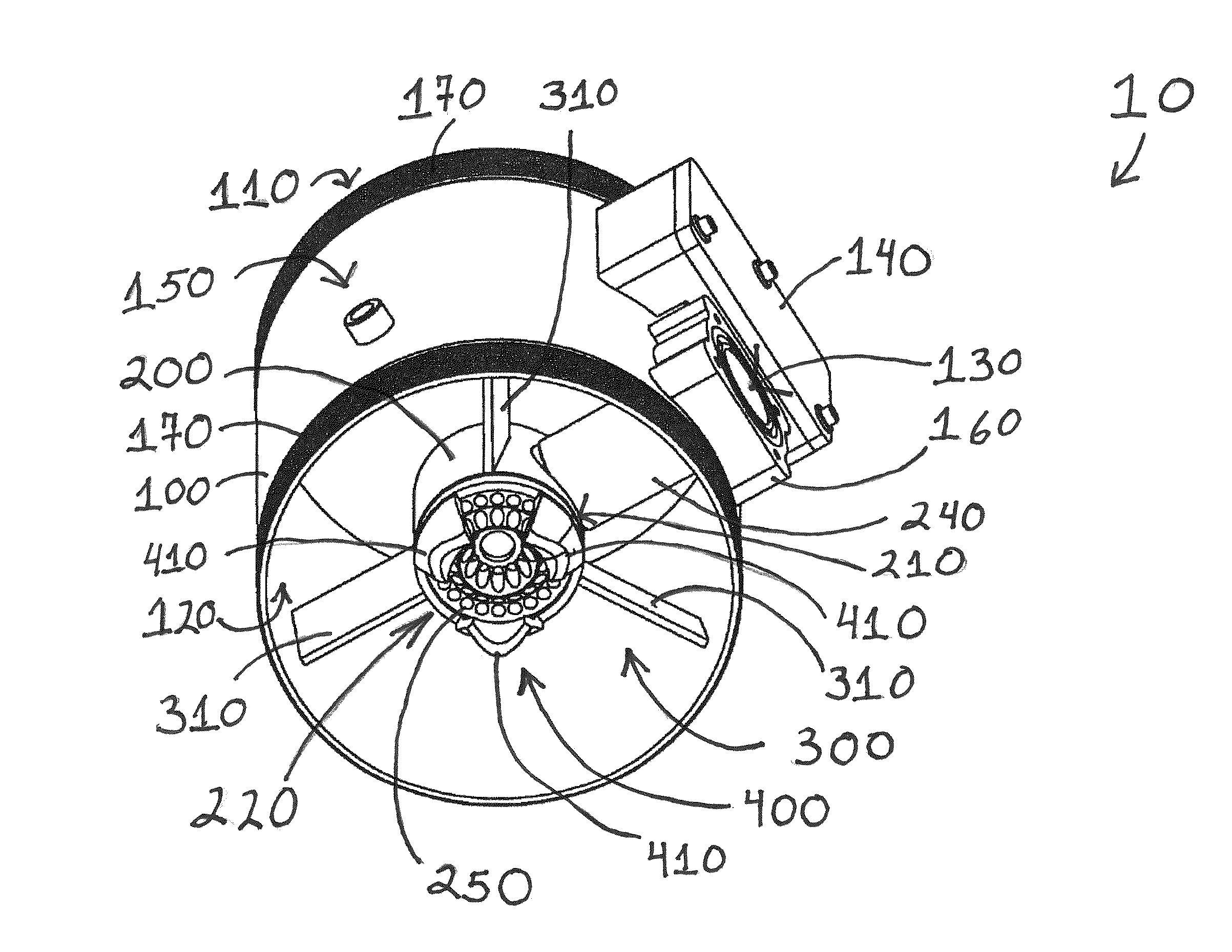
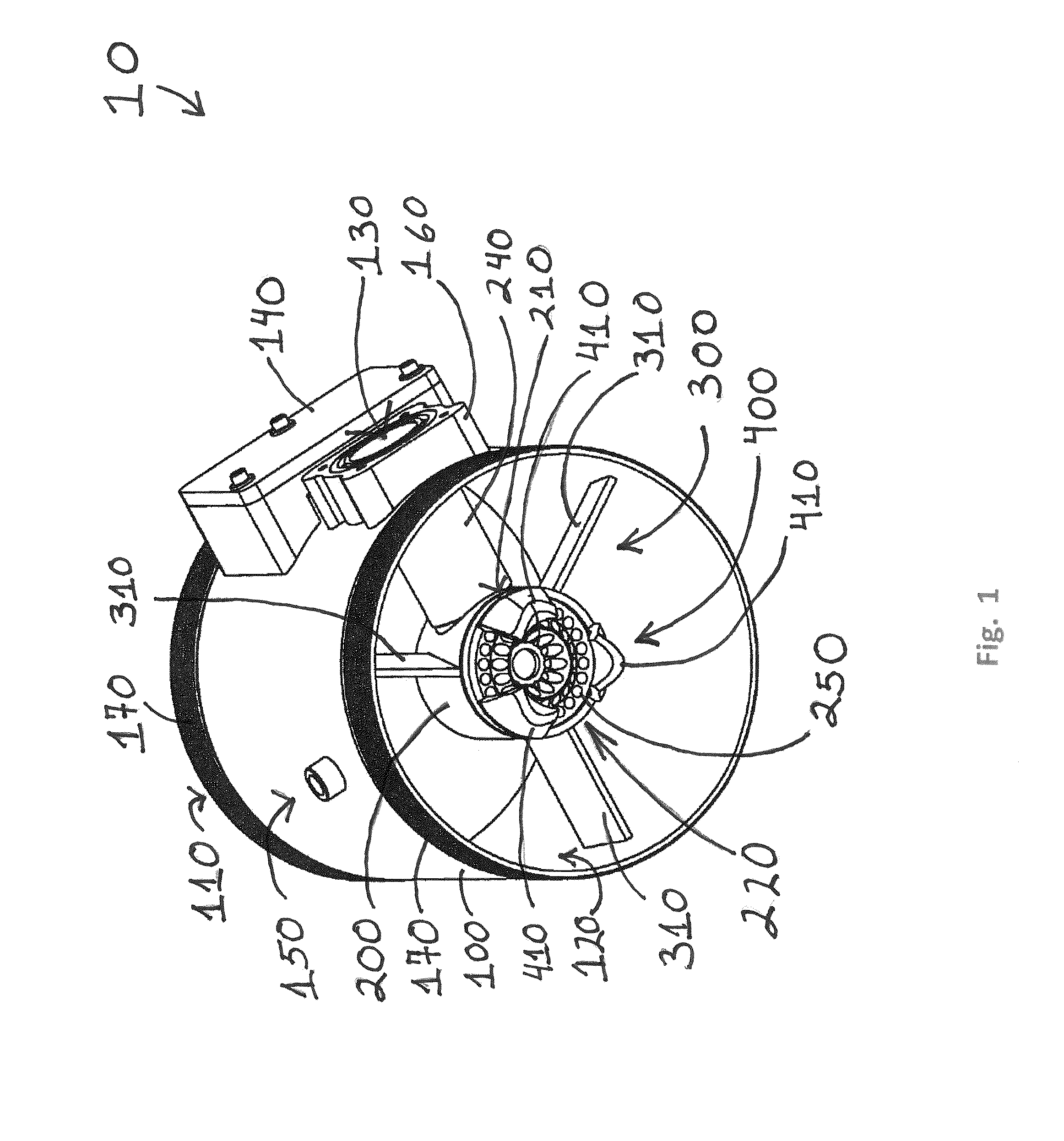
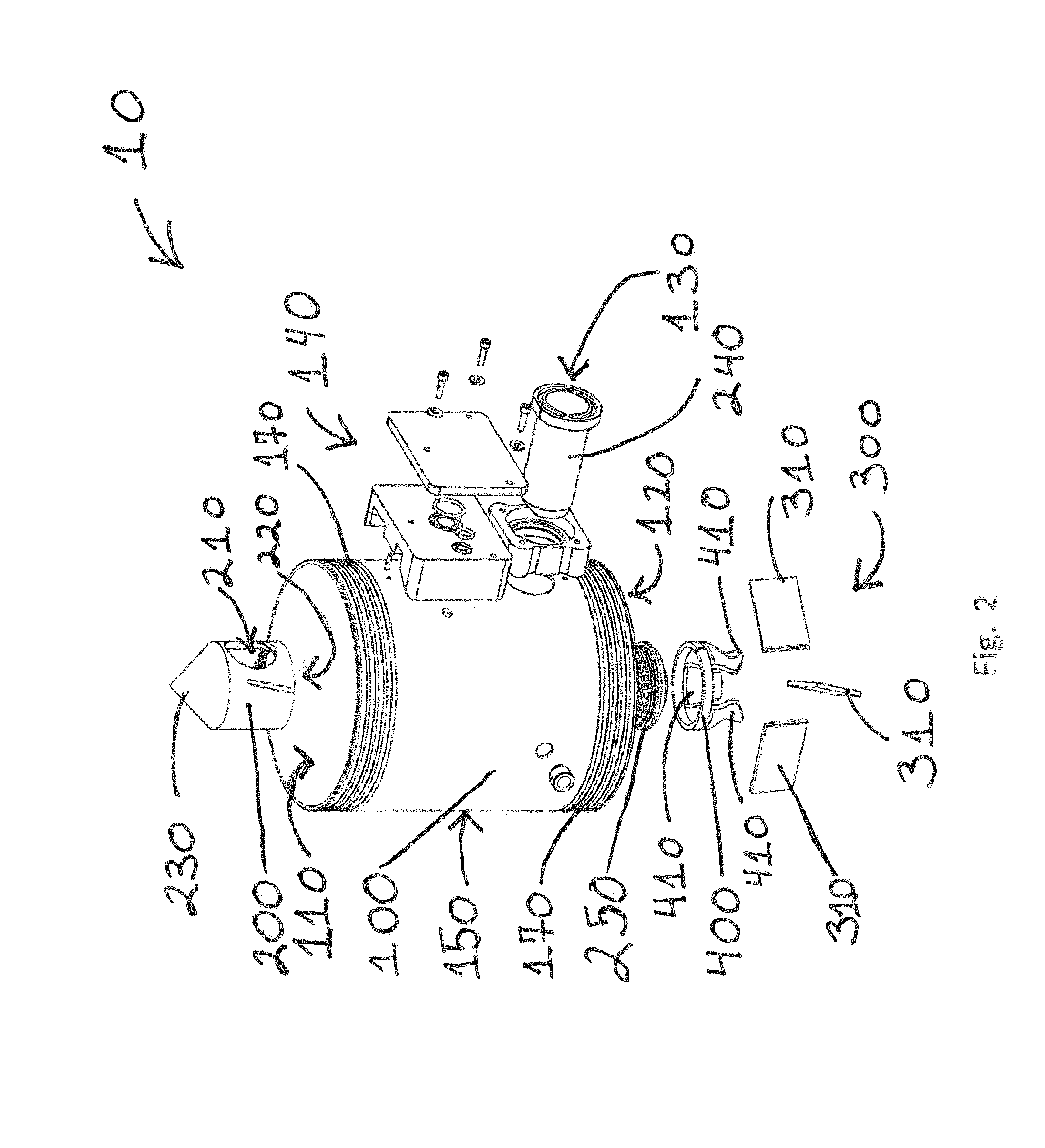
[0031]With reference to FIG. 1, depicted is a perspective view of a mixing assembly 10 in accordance with one embodiment of the present invention. As can be seen, the depicted embodiment comprises a housing 100 of substantially cylindrical configuration, a sidewall 150 encircling a first open end 110 and a second open end 120. In the depicted embodiment, the housing 100 may be disposed within the path of an engine air intake such that ambient air, or a first fluid, to be directed to the combustion chamber of the engine flows through the housing 100 by passing into the first open end 110 and out of the second open end 120.

[0032]As can also be seen in FIG. 1, an injector body 200 is disposed substantially within the flow of the first fluid in order to inject a second fluid within the flow path of the first fluid. In certain embodiments the second fluid may comprise a gaseous fuel such as natural gas, but the present invention is not limited to such second fluids. The second fluid may ...


PUM


Abstract

An embodiment of a mixing assembly for mixing at least two fluids, comprises a housing and an injector body disposed concentrically therein, a vorticing element disposed about the injector body, and a compression element disposed about an outlet of the injector body. The housing is disposed for passage of a first fluid therethrough. The injector body being disposed within the housing and further disposed for the introduction of a second fluid within the flow path of the first fluid.

Description

BACKGROUND OF THE INVENTION[0001]1. Field of the Invention[0002]The present invention relates to mixing assemblies for the mixing of two fluid flows or streams. More specifically, the present invention relates to mixing assemblies for the mixing of two fluids by the metered injection of one fluid into a flow of the other fluid. Furthermore, the present invention is related to mixing assemblies without moving parts.[0003]2. Description of the Related Art[0004]A combustion-ignition engine, such as a compression-ignition engine of the type configured to operate on diesel, or other distillate fuel may also be configured to operate on gaseous fuel, such as natural gas, either in lieu of or supplementing the diesel fuel, though such engines are not necessarily manufactured to operate on natural gas. Thus, generally modifications must be made to the engine in order to provide for the introduction of gaseous fuel to the combustion chamber of the engine. One method of introducing gaseous fue...

Claims


Application Information

Patent Timeline
Patent Type & Authority Applications(United States)
IPC IPC(8): F02M43/04F02M61/16
CPCF02M61/16F02M43/04F02M21/0218Y02T10/30B01F2025/916B01F25/31331B01F25/3131B01F25/313B01F25/10B01F25/4314B01F35/71825B01F2025/931
Inventor GREEN, JASON E.
Owner GREEN JASON E
Why Eureka
Try Eureka