Supercharge Your Innovation With Domain-Expert AI Agents!

Cylinder welding fixture

A welding fixture and cylinder technology, applied in welding equipment, auxiliary welding equipment, welding/cutting auxiliary equipment, etc., can solve problems such as low productivity and uneven welding

Inactive Publication Date: 2021-02-23
湖南顺铭科技有限公司
View PDF3 Cites 0 Cited by
  • Summary
  • Abstract
  • Description
  • Claims
  • Application Information

AI Technical Summary

Problems solved by technology

[0004] Based on this, it is necessary to provide a cylindrical welding fixture for the problems of low productivity and uneven welding

Method used


Image

  • Cylinder welding fixture

Examples


Embodiment Construction

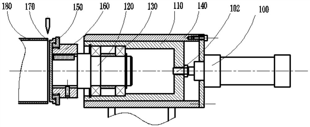
[0014] Below in conjunction with accompanying drawing, the present invention will be further described, as figure 1 As shown, this is a preferred embodiment of the present invention, a cylindrical welding fixture, including a pneumatic clamping device, the pneumatic clamping device includes a cylinder 100, an inner sleeve 110 and a rotating shaft 120, and the cylinder 100 passes through the inner sleeve The sleeve 110 is connected to the rotating shaft 120, and the cylinder rod 102 of the cylinder 100 is connected to the inner sleeve 110 through threads. During the process of adding a back cover 170 to the cylinder 180, the cylinder 100 drives the inner sleeve 110 to place the cylinder on the rotating shaft 120. The bottom cover 170 is pressed into the cylinder 180, and the rotating shaft 120 can rotate freely. During welding, the three-jaw chuck drives the cylinder 180 to rotate, and the bottom cover 170 rotates synchronously with the cylinder 180 to complete the circular seam...


PUM


Abstract

The invention relates to a cylinder welding fixture. The cylinder welding fixture comprises a pneumatic clamping device for clamping a sealing bottom, wherein the pneumatic clamping device comprises an air cylinder, an inner sleeve and a rotating shaft, and the air cylinder is connected with the rotating shaft through the inner sleeve. The air cylinder drives the inner sleeve to press the sealingbottom fixed to the rotating shaft into a cylinder in the process of additionally installing the sealing bottom on the cylinder, the rotating shaft can rotate freely, a three-jaw chuck drives the cylinder to rotate during welding, the sealing bottom synchronously rotates along with the cylinder so as to complete girth welding, the sealing bottom is directly pressed into the cylinder for welding byusing the pneumatic clamping device, automation of welding of the sealing bottom additionally installed on the cylinder is achieved, time can be saved, the production efficiency is improved, and meanwhile, the problem of non-uniform welding caused by spot welding machining is solved.

Description

technical field [0001] The invention relates to a welding jig, in particular to a cylindrical welding jig. Background technique [0002] Metal cylinders with bottoms are widely used in food packaging, decoration, furniture, kitchen utensils and other industries. Since the cylinder bottom cover is not easy to be directly formed by traditional cutting or stamping, welding processing is often used to add the cylinder to the bottom cover. In the process of welding, not only must meet the common requirements of precise positioning, but also fully consider the variability of thin-walled pipe fittings and the thermoplasticity of welding processing. Therefore, the positioning and clamping mechanism and clamping force must be reasonably designed, and appropriate welding processes , in order to adapt to the high quality requirements of the product. [0003] At present, when adding a back cover to the cylinder, the clamping mechanism of the cylinder used is a three-jaw chuck, and the ...

Claims


Application Information

Patent Timeline
IPC IPC(8): B23K37/04B23K37/047
CPCB23K37/0435B23K37/047
Inventor 彭成湘
Owner 湖南顺铭科技有限公司
Features
  • R&D
  • Intellectual Property
  • Life Sciences
  • Materials
  • Tech Scout
  • Unparalleled Data Quality
  • Higher Quality Content
  • 60% Fewer Hallucinations
Learn More