Net forming structure and process of melt-blown cloth

A melt-blown cloth and net-forming technology, which is applied in the field of textile manufacturing, can solve problems such as low product quality and poor drafting effect, and achieve good performance, improved drafting effect, and high controllability

Pending Publication Date: 2021-02-23
宜宾丽雅新材料有限责任公司
View PDF0 Cites 0 Cited by
  • Summary
  • Abstract
  • Description
  • Claims
  • Application Information

AI Technical Summary

Problems solved by technology

[0003] The technical problem to be solved by the present invention is to use hot air alone to draw fibers into a web, the drafting effect is poor, and the product quality is low. The purpose is to provide a web-forming structure and process for melt-blown cloth, and to build a spatial magnetic field in the spinning area. When the fiber is ejected from the spinneret hole, the fiber is drafted simultaneously by hot air and magnetic field, which can greatly improve the drafting effect, thereby achieving the purpose of improving the filtration efficiency of the product

Method used


Image

  • Net forming structure and process of melt-blown cloth

Examples


Embodiment 1

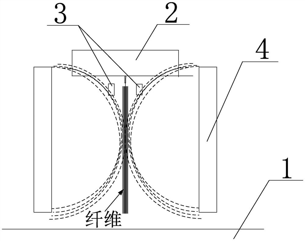
[0022] Such as figure 1 As shown, a web-forming structure of a melt-blown cloth includes a spinneret 2 with a hot air drafting function arranged above the web-forming curtain 1. It is characterized in that the spinneret holes below the spinneret 2 are arranged on both sides There is an electrostatic electret machine 3, and a magnet 4 is arranged between the spinneret 2 and the web-forming curtain 1. The direction of the Lorentz force generated by the magnetic field of the magnet 4 on the fibers is consistent with the direction of movement of the spinneret fibers.

[0023] The web-forming structure of the present invention, by constructing a spatial magnetic field in the spinning area, when the fiber is ejected from the spinneret hole, uses hot air and a magnetic field to simultaneously draft the fiber, which can greatly improve the drafting effect, thereby achieving improved product filtration. effective purpose. The invention utilizes the principle of electromagnetic mutual ...

Embodiment 2

[0028] A web forming process of melt-blown cloth. The fibers are sprayed from the spinneret, and the hot air of the spinneret is used to initially draw the fibers, and the electrostatic electret machine is started to make the sprayed fibers charged and charged. When passing through the magnetic field of the magnet, a vertically downward Lorentz force is generated, and the fiber is double-drawn by the blowing force of the hot air and the Lorentz force of the magnetic field.

[0029] The web-forming process of the present invention adopts the drafting method combining hot air and magnetic field, which can not only avoid the mutual contact and entanglement of fibers, overcome the defects of hot air drafting alone, but also improve the drafting effect, so that the fibers can be It is fully stretched to become finer and improve the quality of web formation.


PUM


Abstract

The invention discloses a net forming structure and process of melt-blown cloth. The net forming structure comprises a spinneret plate which is arranged above a net forming curtain and has a hot air drafting function, wherein electrostatic electrets are arranged on two sides of a spinneret hole in the lower portion of the spinneret plate, a magnet is arranged between the spinneret plate and the net forming curtain, and the direction of a lorentz force generated by a magnetic field of the magnet to a fiber is consistent with the movement direction of the spun fiber. According to the net formingstructure, the space magnetic field is constructed in a spinning area, when the fiber is sprayed out of the spinneret hole, hot air and the magnetic field are used for conducting drafting treatment on the fiber at the same time, the drafting effect can be greatly improved, and therefore the purpose of improving the product filtering effect is achieved.

Description

technical field [0001] The invention relates to the field of textile manufacturing, in particular to a web-forming structure and process of melt-blown cloth. Background technique [0002] At present, the melt-blown industry generally uses spinneret hot air to draw fibers into webs. This process is easily affected by ambient temperature, spinneret, and raw materials. The change of the material will cause deformation and breakage, and they will be entangled before the net is formed, and the drafting effect is affected by the hot air. value. Contents of the invention [0003] The technical problem to be solved by the present invention is to use hot air alone to draw fibers into a web, the drafting effect is poor, and the product quality is low. The purpose is to provide a web-forming structure and process for melt-blown cloth, and to build a spatial magnetic field in the spinning area. When the fiber is ejected from the spinneret hole, the fiber is drawn by hot air and magn...

Claims


Application Information

Patent Timeline
Patent Type & Authority Applications(China)
IPC IPC(8): D04H1/56D01D5/098
CPCD04H1/56D01D5/0985D01D5/098
Inventor 包尕军范贤珍黄盛国张丹李开国
Owner 宜宾丽雅新材料有限责任公司
Why Eureka
Try Eureka