Aeroengine core machine, control method and aeroengine

An aero-engine and core engine technology, applied in the field of aero-engines, can solve the problems that the engine does not have the ability to adapt to different working conditions, increases the cost of engine design and implementation difficulty, and requires high temperature resistance of high-temperature components, so as to achieve self-adaptation performance, reduce design cost, and improve economy

Active Publication Date: 2022-07-12
AECC COMML AIRCRAFT ENGINE CO LTD
View PDF0 Cites 0 Cited by
  • Summary
  • Abstract
  • Description
  • Claims
  • Application Information

AI Technical Summary

Problems solved by technology

For example, the outlet temperature of the combustion chamber is relatively high during take-off conditions. In order to meet the operating requirements of this condition, the high-temperature components of the engine need to be made of materials with relatively high temperature resistance, which greatly increases the design cost and implementation of the engine. Difficulty, which also limits its service life; and in typical air conditions such as cruising, the thrust required by the engine is relatively low compared with take-off conditions, and the outlet temperature of the combustion chamber is relatively low at this time. If only for For engine design in air conditions such as cruising, the restrictions on the materials used for high-temperature parts of the engine can be appropriately relaxed
[0004] At present, most engines do not have the ability to adapt to different working conditions, and have high requirements for the temperature resistance of high-temperature components

Method used


Image

  • Aeroengine core machine, control method and aeroengine
  • Aeroengine core machine, control method and aeroengine
  • Aeroengine core machine, control method and aeroengine

Examples


Embodiment Construction

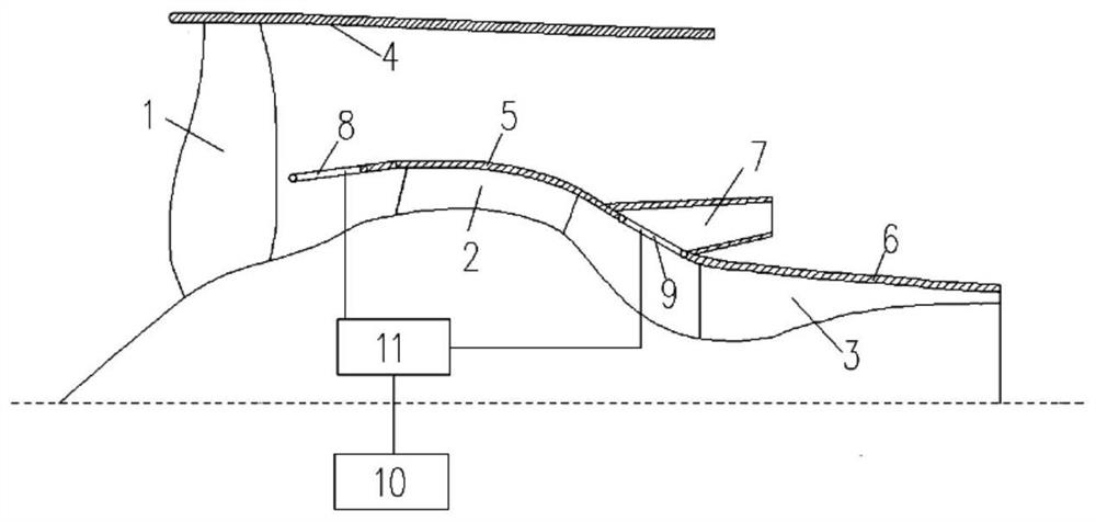
[0033] The technical solutions in the embodiments will be clearly and completely described below with reference to the accompanying drawings in the embodiments of the present invention. Obviously, the described embodiments are only some, but not all, embodiments of the present invention. Based on the embodiments of the present invention, all other embodiments obtained by those of ordinary skill in the art without creative work fall within the protection scope of the present invention.

[0034] In the description of the present invention, it should be understood that the terms "center", "horizontal", "portrait", "front", "rear", "left", "right", "top", "bottom", " The orientation or positional relationship indicated by vertical, horizontal, top, bottom, inner, outer, etc. is based on the orientation or positional relationship shown in the drawings, and is only for the convenience of describing the present invention and The description is simplified rather than indicating or im...


PUM


Abstract

The invention relates to an aero-engine core machine, a control method and an aero-engine, wherein the aero-engine core machine comprises a fan, a low-pressure compressor, a high-pressure compressor, a nozzle, a first movable part and a second movable part, and the low-pressure compressor It is arranged downstream of the fan; the first movable part is arranged between the fan and the low-pressure compressor, and is used to adjust the bypass ratio of the core engine of the aero-engine through its own motion; the high-pressure compressor is arranged downstream of the low-pressure compressor; the nozzle pipe It is arranged between the low-pressure compressor and the high-pressure compressor, and is used for exporting the outlet air flow of the low-pressure compressor; the second movable part is arranged at the inlet of the nozzle, and is used to open or close the inlet of the nozzle. The aero-engine includes the above-mentioned core engine. The present invention can realize the adaptability to different operating conditions of the engine through the cooperation of the first movable element and the second movable element.

Description

technical field [0001] The invention relates to the technical field of aero-engines, in particular to an aero-engine core machine, a control method and an aero-engine. Background technique [0002] In the currently widely used turbofan engine with a large bypass ratio, the internal air flow will pass through the fan connotation that initially compresses the air flow, the low-pressure compressor and high-pressure compressor for further compression, and the fan that heats it. The high temperature and high pressure air flow formed in the combustion chamber then drives the high and low pressure turbines of the high pressure compressor and the fan (including the low pressure compressor) in turn, as well as the inner nozzle that allows the airflow to be ejected at high speed; Finally, it flows out from the extrinsic nozzle to generate corresponding thrust. [0003] For a high bypass ratio turbofan engine, economic optimization requires that the engine is designed with a higher bo...

Claims


Application Information

Patent Timeline
Patent Type & Authority Patents(China)
IPC IPC(8): F02K3/06F02K3/075F02C7/057F02C9/18
CPCF02K3/06F02K3/075F02C7/057F02C9/18Y02T50/60
Inventor 李华雷郑恒严红明谭智勇
Owner AECC COMML AIRCRAFT ENGINE CO LTD
Why Eureka
Try Eureka