Low-noise axial flow fan

An axial flow fan and low noise technology, applied in axial flow pumps, mechanical equipment, machines/engines, etc., can solve the problems of high noise and difficult heat dissipation of motors, and achieve the effect of improving heat dissipation performance and shock absorption effect

Inactive Publication Date: 2021-02-23
刘静
View PDF0 Cites 2 Cited by
  • Summary
  • Abstract
  • Description
  • Claims
  • Application Information

AI Technical Summary

Problems solved by technology

[0004] The purpose of the present invention is to solve the problem that the motor of the axial flow fan in the prior art is not easy to dissipate heat and has a large noise, and proposes a low-noise axial flow fan

Method used


Image

  • Low-noise axial flow fan
  • Low-noise axial flow fan
  • Low-noise axial flow fan

Examples


Embodiment 1

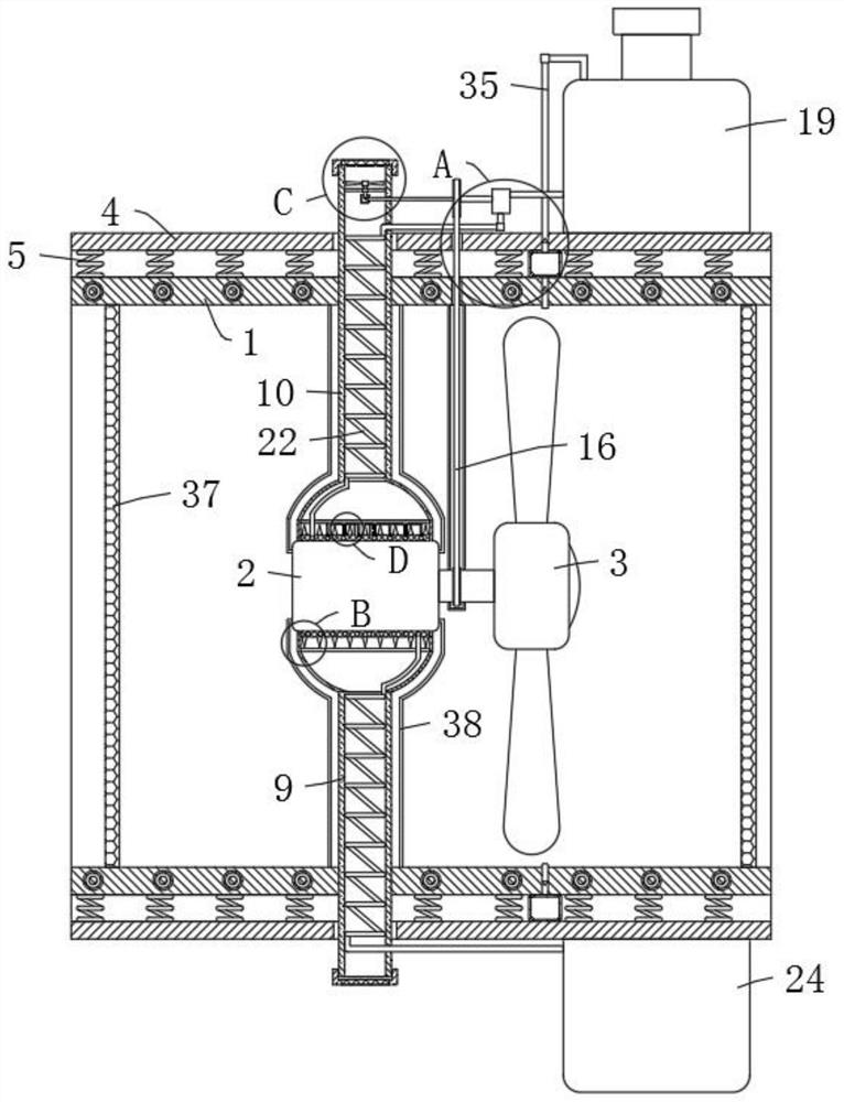
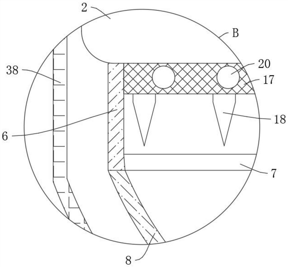
[0032] refer to Figure 1-6 , a low-noise axial flow fan, including an inner cylinder 1, a motor 2 is fixedly installed inside the inner cylinder 1 through a bracket, safety nets 37 are fixedly installed at both ends of the inner cylinder 1, and the end of the output shaft of the motor 2 The fan blade 3 is fixedly installed, the outer wall of the inner cylinder 1 is covered with an outer cylinder 4, the inner cylinder 1 and the outer cylinder 4 are elastically connected by a plurality of evenly distributed buffer springs 5, and the circumference of the motor 2 The outer wall fixing sleeve is provided with an air collecting cylinder 6, the upper and lower ends of the air collecting cylinder 6 are fixedly connected with the air collecting hood 8, and the upper and lower ends of the air collecting cylinder 6 are provided with ventilation slots corresponding to the air collecting hood 8 7. The inlet ends of the two wind collecting hoods 8 are respectively fixedly connected with th...

Embodiment 2

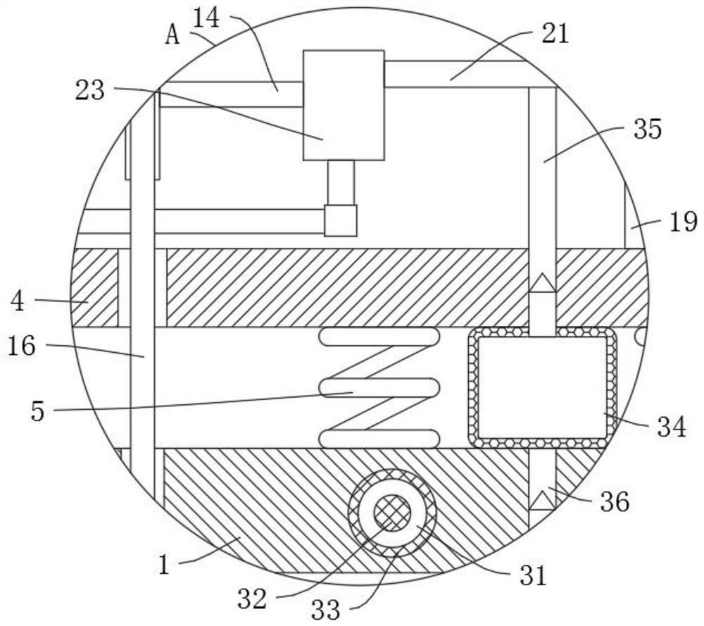
[0037] refer to figure 1 and Figure 4 , is basically the same as Embodiment 1, furthermore: the ventilation device includes a rotating rod 12 connected in the air inlet pipe 10 through a cross bar 11, the upper end of the rotating rod 12 is fixedly connected with a ventilation fan blade 13, and the air inlet pipe 10 The side wall of the drive shaft 14 is rotatably connected to the drive shaft 14, the left end of the drive shaft 14 is meshed with the lower end of the rotating rod 12 through two gears 15, and the other end of the rotating rod 12 is connected to the output shaft of the motor 2 through a chain drive 16. , the motor 2 will also drive the transmission shaft 14 to rotate through the chain transmission 16, and the transmission shaft 14 will also drive the input shaft of the water pump 23 to rotate, so the water pump 23 will pump the water in the upper water tank 19 into the lower water tank 24 through the delivery pipe 21, and then transport During this period, the ...

Embodiment 3

[0039] refer to Figure 1-3 and Figure 6 , is basically the same as Embodiment 1, furthermore: the water circulation device includes a heat conduction cylinder 17 fixedly connected to the outer wall of the motor 2, the heat conduction cylinder 17 is fixedly connected with a first helical tube 20, and the two ends of the first helical tube 20 Both are connected with delivery pipes 21, and the other ends of the two delivery pipes 21 are fixedly connected with the upper water tank 19 and the lower water tank 24 respectively. The middle part of the delivery pipe 21 on the side wall of the water tank 19 is fixedly equipped with a water pump 23, and the right end of the transmission shaft 14 is connected with the water pump 23. The input shaft of the upper water tank 19 and the lower water tank 24 are fixedly connected and communicated through a plurality of connecting pipes 25, an emergency cooling device is arranged between the heat conduction cylinder 17 and the first spiral pip...


PUM


Abstract

The invention relates to the technical field of axial flow fans, in particular to a low-noise axial flow fan. The low-noise axial flow fan comprises an inner cylinder, wherein a motor is fixedly installed in the inner cylinder through a support, fan blades are fixedly installed at the tail end of an output shaft of the motor, and the circumferential outer wall of the inner cylinder is sleeved withan outer cylinder. The inner cylinder and the outer cylinder are elastically connected through a plurality of evenly-distributed buffer springs, the circumferential outer wall of the motor is fixedlysleeved with an air collecting cylinder, the upper end and the lower end of the air collecting cylinder are both fixedly connected with air collecting covers, and the inlet ends of the two air collecting covers are fixedly connected with an air outlet pipe and an air inlet pipe correspondingly. A ventilation device connected with the motor is arranged in the air inlet pipe. An upper water tank and a lower water tank are arranged on the upper side wall and the lower side wall of the outer cylinder correspondingly. A water circulation device is arranged between the upper water tank and the motor. When the low-noise axial flow fan works, heat dissipation can be effectively conducted on the motor, and the low-noise axial flow fan also has a good damping capability.

Description

technical field [0001] The invention relates to the technical field of axial flow fans, in particular to a low-noise axial flow fan. Background technique [0002] Axial flow fans have a wide range of uses, that is, the airflow in the same direction as the axis of the fan blades, such as electric fans and air conditioner external fans are axial flow fans. It is called "axial flow" because the gas flows parallel to the shaft of the fan. Axial flow fans are usually used in occasions with high flow requirements and low pressure requirements. [0003] Due to the structure of the axial flow fan, when the axial flow fan extracts room temperature, the extracted air can cool the motor inside the fan, but the air extracted by some axial flow fans has been heated, and the motor cannot dissipate heat in this case. , There will also be high temperature faults, and the axial flow fan will have greater vibration and noise during long-term work. Contents of the invention [0004] The p...

Claims


Application Information

Patent Timeline
Patent Type & Authority Applications(China)
IPC IPC(8): F04D25/08F04D19/00F04D29/58F04D29/66
CPCF04D19/002F04D25/082F04D29/5806F04D29/584F04D29/5846F04D29/668
Inventor 刘静姜迪张磊
Owner 刘静
Why Eureka
Try Eureka