Spray cooling gas injection sintering machine and its control method

A control method and sintering machine technology, which is applied in the field of metallurgy, can solve the problems of insignificant strengthening sintering effect, rising defective rate of sintering ore, easy burning of pipe row facilities in the hood, etc.

Active Publication Date: 2022-06-07
ZHONGYE-CHANGTIAN INT ENG CO LTD
View PDF6 Cites 0 Cited by
  • Summary
  • Abstract
  • Description
  • Claims
  • Application Information

AI Technical Summary

Problems solved by technology

[0006] 1) If the starting point of gas injection is set too early, it is easy to catch fire on the material surface
[0007] If the starting point of gas injection is set too close to the head of the sintering machine, the red hot material surface just out of the ignition furnace will easily ignite the injected gas, so that not only the gas will not strengthen the sintering effect, but also it will easily burn the inner tube of the hood Row facilities, affecting normal production
[0008] 2) If the starting point of gas injection is set, the enhanced sintering effect will not be obvious
[0009] If the starting point of gas injection is set, the ignition phenomenon can be effectively suppressed. However, since the sintering machine is produced by draft operation, the upper material layer does not have the effect of hot air heat storage, which is the area most in need of supplementary heat.
However, if the gas is injected too late, the combustion zone has already moved down to the middle of the material layer, and the upper material layer cannot be supplemented by gas, so that the overall gas injection enhanced sintering effect is not obvious, and even defective sintered ore may appear. rising rate phenomenon
[0010] To sum up, the current gas injection technology has key problems to be solved in the selection of the injection starting point

Method used


Image

  • Spray cooling gas injection sintering machine and its control method
  • Spray cooling gas injection sintering machine and its control method
  • Spray cooling gas injection sintering machine and its control method

Examples


Embodiment Construction

[0044] The invention intends to solve the problem in the prior art that the starting point of gas injection cannot be moved forward without igniting.

[0045] In order to enable those skilled in the art to better understand the solution of the present invention, the present invention will be further described in detail below in conjunction with the accompanying drawings and specific embodiments.

[0046]In this article, terms such as "upper, lower, inner, outer" are established based on the positional relationship shown in the drawings, and the corresponding positional relationship may also change accordingly depending on the drawings. It is understood as an absolute limitation on the scope of protection; moreover, relative terms such as "first" and "second" are only used to distinguish one from another component with the same name, and do not necessarily require or No such actual relationship or order between these components is implied.

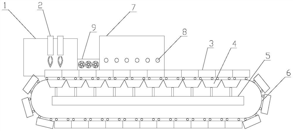
[0047] Please refer to figure 1 , ...


PUM


Abstract

The invention discloses a spray cooling type gas injection sintering machine and a control method thereof. The sintering machine comprises a sintering machine rail, a sintering machine trolley arranged on the sintering machine rail, an ignition device located at the head of the sintering machine, and a gas injection blowing device, the gas injection device is set at the gas injection position of the sintering machine to blow gas to the sintering material surface of the sintering machine trolley when the sintering machine trolley passes by its position; further comprising A spraying device, the spraying device is arranged at a position between the ignition device and the gas injection device, so as to spray the sintered material surface of the sintering machine trolley when the sintering machine trolley passes by its position Blow atomized water. The sintering machine is equipped with a spray device for the problems of easy ignition and unstable production existing in the gas injection device, which can effectively avoid the above problems.

Description

technical field [0001] The invention relates to the technical field of metallurgy, in particular to a gas injection sintering machine with spray cooling function used in the production process of sintered ore. The invention also relates to a method for controlling said gas injection sintering machine. Background technique [0002] The sintering process is a key link in the ironmaking process. Its principle is to mix various powdery iron-containing raw materials with an appropriate amount of fuel and flux, add an appropriate amount of water, mix and pelletize the material on the sintering equipment to make the material A series of physical and chemical changes, sintered into blocks, which are sent to the blast furnace for the next step. [0003] Sintering is the main raw material processing technology for iron and steel smelting in my country, and more than 75% of blast furnace raw materials come from sintering ore. But sintering is a typical high energy consumption and hig...

Claims


Application Information

Patent Timeline
Patent Type & Authority Patents(China)
IPC IPC(8): F27B21/00F27B21/08F27B21/14F27D9/00F27D19/00
CPCF27B21/00F27D9/00F27D19/00F27D2009/0086F27D2019/0056Y02P10/25
Inventor 周浩宇叶恒棣刘前魏进超
Owner ZHONGYE-CHANGTIAN INT ENG CO LTD
Why Eureka
Try Eureka