Optical lens and imaging device

A technology of optical lens and imaging surface, which is applied in the field of imaging lens, can solve the problems of increased influence of imaging quality, high sensitivity of product structure, and influence of imaging quality, etc. The effect of balancing

Active Publication Date: 2021-02-23
JIANGXI LIANYI OPTICS CO LTD
View PDF6 Cites 6 Cited by
  • Summary
  • Abstract
  • Description
  • Claims
  • Application Information

AI Technical Summary

Problems solved by technology

[0003] However, the inventor found in the research of the existing camera lens that in order to improve the imaging performance of the lens, on the one hand, it is achieved by increasing the number of lenses, usually 6-7 lenses are designed, which leads to a larger lens size and a lower cost. Higher, and the presence of ghosts affects the image quality; on the other hand, the use of complex optical lens design results in high sensitivity to product structure, increased processing difficulty, and the impact of ambient light on image quality increase

Method used


Image

  • Optical lens and imaging device
  • Optical lens and imaging device
  • Optical lens and imaging device

Examples


no. 1 example

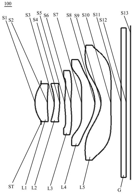
[0069] see figure 2 , an optical lens 100 provided by the first embodiment of the present invention includes, from the object side to the imaging surface in sequence: a stop ST, a first lens L1, a second lens L2, a third lens L3, a fourth lens L4, a fifth lens Lens L5 and filter G.

[0070] The first lens L1 has positive refractive power, the object side S1 of the first lens is a convex surface, the image side S2 of the first lens is concave, and the image side S2 of the first lens has an inflection point;

[0071] The second lens L2 has negative refractive power, the object side S3 of the second lens is concave, and the image side S4 of the second lens is convex;

[0072] The third lens L3 has positive refractive power, the object side S5 of the third lens is convex at the near optical axis, and the image side S6 of the third lens is concave at the near optical axis;

[0073] The fourth lens L4 has positive refractive power, the object side S7 of the fourth lens is convex ...

no. 2 example

[0087] The optical lens provided in this embodiment is substantially the same as the optical lens 100 in the first embodiment, except that the design parameters of each lens are different, and the relevant parameters of each lens are shown in Table 3.

[0088] table 3

[0089]

[0090] The parameters of each lens aspheric surface in this embodiment are shown in Table 4.

[0091] Table 4

[0092]

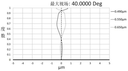
[0093] Please refer to Image 6 , Figure 7 and Figure 8 , respectively show the vertical axis chromatic aberration curve, distortion curve, and L1 internal reflection ghost light path diagram of the optical lens in this embodiment.

[0094] from Image 6 It can be seen from the figure that the vertical chromatic aberration between the longest wavelength and the shortest wavelength is controlled within ±1 micron, which shows that the vertical chromatic aberration of the optical lens in this embodiment is well corrected.

[0095] from Figure 7 It can be seen from the fi...

no. 3 example

[0098] The optical lens provided by this embodiment is substantially the same as the optical lens 100 of the first embodiment, except that the third lens has a negative refractive power, the structure of the fourth lens L4 is different, and the design parameters of each lens are different, specifically The edge sagittal height on the image side S8 of the fourth lens is a bit larger, which is beneficial to correct aberrations and improve imaging quality.

[0099] Specifically, the design parameters of the optical lens provided in this embodiment are shown in Table 5.

[0100] table 5

[0101]

[0102] The aspheric parameters of each lens in the optical lens in this embodiment are shown in Table 6.

[0103] Table 6

[0104]

[0105] Please refer to Figure 9 , Figure 10 and Figure 11 , respectively show the vertical axis chromatic aberration curve, distortion curve, and L1 internal reflection ghost light path diagram of the optical lens in this embodiment.

[0106]...


PUM


Abstract

The invention discloses an optical lens and imaging equipment. The optical lens sequentially comprises a diaphragm, a first lens, a second lens, a third lens, a fourth lens, a fifth lens and an optical filter from an object side to an imaging surface along an optical axis, wherein the object side surface of the first lens is a convex surface, and the image side surface of the first lens is a concave surface; the object side surface of the second lens is a concave surface, and the image side surface of the second lens is a convex surface near the optical axis; the object side surface of the third lens is a convex surface near the optical axis, and the image side surface of the third lens is a concave surface near the optical axis; the fourth lens has positive focal power, and the image sidesurface of the fourth lens is a convex surface; the fifth lens has negative focal power, the object side surface and the image side surface of the fifth lens are both concave surfaces near the optical axis, and the object side surface and the image side surface of the fifth lens are both provided with at least one inflection point; the optical filter is further arranged. the first lens, the second lens, the third lens, the fourth lens and the fifth lens are aspheric lenses. According to the optical lens, the influence of ghosting on the imaging quality can be reduced, and the balance of highpixel and miniaturization is realized.

Description

technical field [0001] The invention relates to the technical field of imaging lenses, in particular to an optical lens and imaging equipment. Background technique [0002] At present, with the popularity of portable electronic devices and the popularity of social networking, video, and live broadcast software, people are more and more fond of photography. Camera lenses have become standard equipment for electronic equipment, and camera lenses have even become consumers The first index to consider when purchasing electronic equipment. In recent years, with the continuous development of the design level and manufacturing and processing technology, the camera lens is constantly developing towards the direction of small size, light weight and high performance. [0003] However, the inventor found in the research of the existing camera lens that in order to improve the imaging performance of the lens, on the one hand, it is achieved by increasing the number of lenses, usually 6...

Claims


Application Information

Patent Timeline
Patent Type & Authority Applications(China)
IPC IPC(8): G02B13/00G02B13/18
CPCG02B13/0045
Inventor 徐丽丽刘绪明曾昊杰曾吉勇
Owner JIANGXI LIANYI OPTICS CO LTD
Why Eureka
Try Eureka