Vacuum glue injection device and glue injection method of capacitor

A technology of glue injection device and capacitor, which is applied to the device and coating of the surface coating liquid, which can solve the problems of large flow resistance, micro leakage of the delivery pump, easy suction and flattening, etc., and achieve the effect of consistent air pressure

Pending Publication Date: 2021-02-26
宁波海融电器有限公司
View PDF3 Cites 5 Cited by
  • Summary
  • Abstract
  • Description
  • Claims
  • Application Information

AI Technical Summary

Problems solved by technology

[0006] Using the above-mentioned glue injection device and its glue injection method can avoid defects such as gaps and air bubbles after the capacitor glue is injected to a certain extent, but due to the saturated vapor pressure of the insulating glue itself and the micro-leakage of the delivery pump, etc., in the vacuum Bubbles are still mixed in the insulating glue in the state, and because the components in the capacitor shell are relatively tight, there will be a gap inside which the flow resistance is relatively large and the insulating glue is difficult to enter.
In addition, the wall thickness of the general capacitor shell is only 1-4mm, and there should be no large pressure difference between the inside and outside of the capacitor shell, otherwise it is easy to be flattened and bulging, so the existing vacuum glue injection device and glue injection method cannot allow the insulating glue to fully enter The above-mentioned gaps with relatively large flow resistance still need further improvement

Method used


Image

  • Vacuum glue injection device and glue injection method of capacitor
  • Vacuum glue injection device and glue injection method of capacitor

Examples


Embodiment Construction

[0029] The present invention will be further described in detail below in conjunction with the accompanying drawings and embodiments.

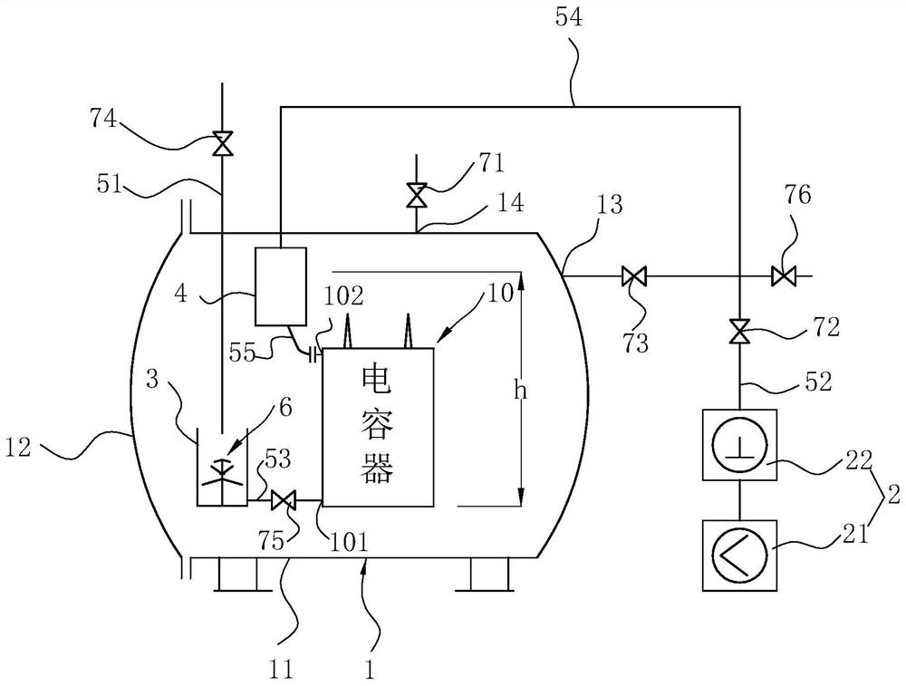
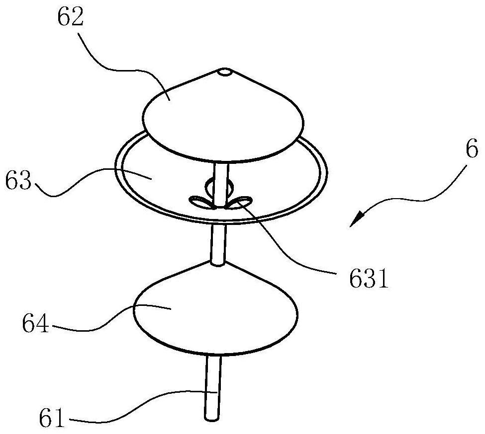
[0030] like figure 1 and figure 2 Shown is a preferred embodiment of the glue injection device of the present invention. The vacuum glue injection device of the capacitor includes a glue injection tank 1, a vacuum pump 2, a degassing barrel 3, a glue filling tank 4, and a glue injection tube 51, wherein the glue injection tank 1 can accommodate at least one capacitor 10, and the glue injection tank 1 The specific size of the volume can be set according to production needs. For simplicity and convenience of description, only one capacitor is shown in the figure. The glue injection tank 1 can adopt a conventional vacuum tank structure, that is, a tank door 12 that is sealed with the tank body 11 is configured, and the tank body 11 is provided with an air extraction port 13, an air release port 14 controlled by an air release valve 71, and a v...


PUM

PropertyMeasurementUnit
porosityaaaaaaaaaa

Abstract

The invention relates to a vacuum glue injection device of a capacitor. The vacuum glue injection device is improved on the basis of the existing glue injection tank, vacuum pump, glue injection pipeand the like, namely a degassing barrel with an open opening and a closed glue supplementing tank are also arranged in the glue injection tank; the glue injection pipe extends into the glue injectiontank and then is inserted into the degassing barrel; the degassing barrel communicates with a capacitor shell through a glue conveying pipe with a glue injection valve; an air inlet and outlet valve is arranged on an air suction pipe between a vacuumizing valve and an air suction opening; the upper part of the glue supplementing tank communicates with the air suction pipe through a connecting pipe; the lower part of the glue supplementing tank communicates with the capacitor shell through a glue supplementing pipe; the air suction pipe between the air inlet and outlet valve and the vacuumizingvalve is also connected with a high-pressure air source through a pressurizing valve; and meanwhile, an air relief opening controlled by an air relief valve is also formed in the glue injection tank.The invention also discloses a glue injection method adopting the vacuum glue injection device. By adopting the vacuum glue injection device and the glue injection method, gaps and bubbles in the capacitor can be effectively eliminated, and the glue injection quality of the capacitor can be obviously improved, so that the vacuum glue injection device and the glue injection method are worthy of popularization and application.

Description

technical field [0001] The invention relates to the technical field of a capacitor manufacturing device and a manufacturing method thereof, in particular to a capacitor vacuum glue injection device and a glue injection method. Background technique [0002] With the rapid development of power technology, large-capacity, high-voltage dry-type power capacitors are more and more widely used, and the requirements for dry-type power capacitors are also getting higher and higher. The quality of the potting glue for power capacitors directly affects the performance of dry-type power capacitors. For this reason, when potting glue, it is required that the insulating glue (generally epoxy resin or polyurethane) that plays an insulating and protective role must be tightly filled in the capacitor shell, that is, the components and components of the capacitor that are tightly filled in the shell Between the insulating part and the shell, after ensuring that it is filled, it is cured. Aft...

Claims


Application Information

Patent Timeline
Patent Type & Authority Applications(China)
IPC IPC(8): B05C5/00B05C11/10B05C11/11
CPCB05C5/002B05C11/10B05C11/1013B05C11/1047B05C11/11
Inventor 于智强
Owner 宁波海融电器有限公司
Why Eureka
Try Eureka