
Grinding and polishing device

A polishing device and a technology for fixing the base, which are applied in the direction of grinding drive devices, grinding/polishing equipment, grinding machines, etc., can solve the problems of dangerous operation, difficult fixing of sandpaper, and easy rubbing by workpieces, etc., to reduce the linear speed, device Safe and reliable effect

Pending Publication Date: 2021-02-26
任峰
View PDF0 Cites 8 Cited by
  • Summary
  • Abstract
  • Description
  • Claims
  • Application Information

AI Technical Summary

Problems solved by technology

[0005] Aiming at the deficiencies of the prior art, the present invention provides a grinding and polishing device, which solves the need to grind and polish small parts in mechanical processing. At present, when performing grinding and polishing operations, workers need to manually hold and polish the workpiece on the grinding machine. Grinding, the operation is more dangerous, and the sandpaper of the grinding machine is not easy to fix, and it is easy to be rubbed up by the workpiece

Method used


Image

  • Grinding and polishing device
  • Grinding and polishing device
  • Grinding and polishing device

Examples


Embodiment 1

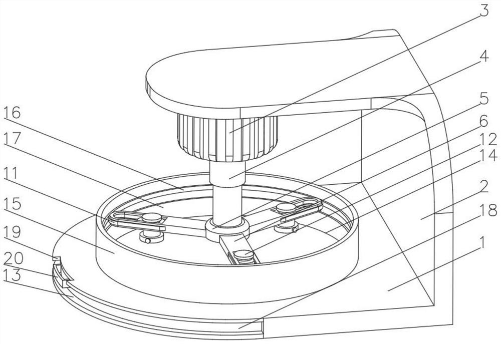
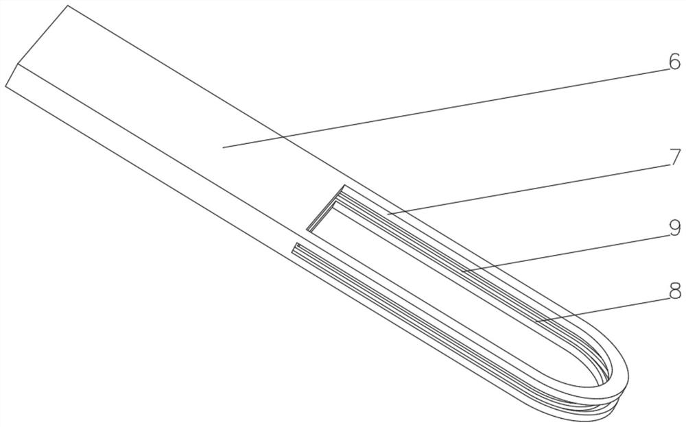
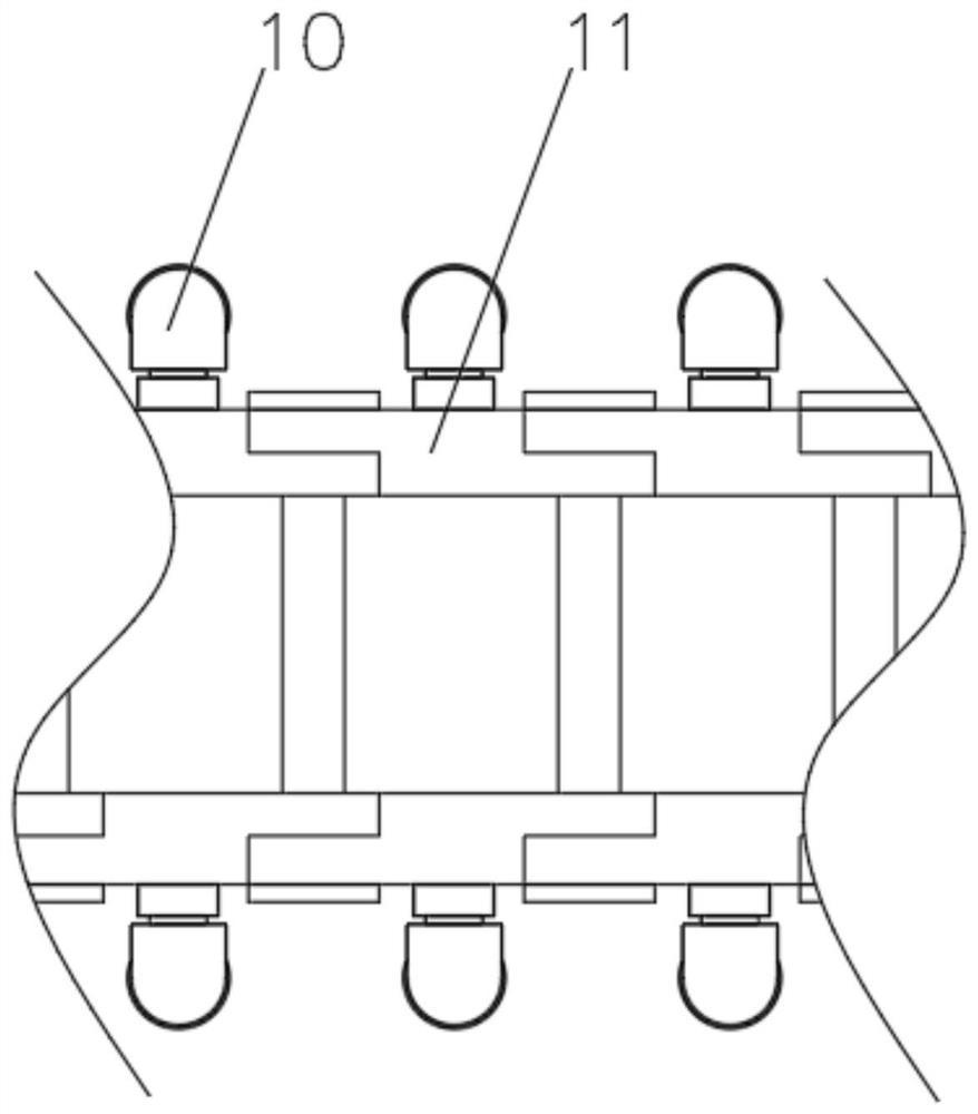
[0032] see Figure 1-5, the present invention provides a technical solution: a grinding and polishing device, comprising a fixed base 1, a support 2 is fixedly connected to one side of the top of the fixed base 1, a drive motor 3 is fixedly connected to the bottom of the support 2, and the drive shaft of the drive motor 3 is fixedly connected to There is a telescopic rod 4, the end of the telescopic rod 4 away from the drive motor 3 is fixedly connected to the control panel 5, the side of the control panel 5 is fixedly connected to the support rod 6, and the top of the end of the support rod 6 away from the control panel 5 is provided with a sliding hole 7, the sliding hole 7 The inner wall is provided with a slideway 8, and both sides of the inner wall of the slideway 8 are provided with a chute 9, and the inner wall of the chute 9 is slidingly connected with a double-headed pulley 10, and the bottom side of the double-headed pulley 10 runs through the chute 9 and extends to t...

Embodiment 2

[0036] see Figure 1-6 On the basis of Embodiment 1, the present invention provides a technical solution: the fixing device 12 includes a fixed plate 121, the top of the fixed plate 121 penetrates and is fixedly connected with a rotating column 122, the bottom of the rotating column 122 is fixedly connected with a clamp 123, and the rotating column 122 The part inside the fixed plate 121 runs through and is fixedly connected with a gear 124, the top of the rotating column 122 is fixedly connected with a guide plate 125, one side of the fixed plate 121 is fixedly connected with an electric telescopic rod 126, and both sides of the fixed plate 121 extend to the slideway 8 It is inside and slidingly connected with the inner wall of the slideway 8. Both sides of the gear 124 pass through the fixed plate 121 and extend to the inside of the slideway 8. The part of the gear 124 located inside the slideway 8 meshes with the tooth chain 11. The electric telescopic rod 126 is connected t...


PUM


Abstract

The invention discloses a grinding and polishing device. The device comprises a fixing base, wherein a support is fixedly connected to one side of the top of the fixing base, a driving motor is fixedly connected to the bottom of the support, a telescopic rod is fixedly connected to a driving shaft of the driving motor, a control panel is fixedly connected to the end, away from the driving motor, of the telescopic rod, a supporting rod is fixedly connected to the side face of the control panel, a sliding hole is formed in the top of the end, away from the control panel, of the supporting rod, asliding way is formed in the inner wall of the sliding hole, sliding grooves are formed in the two sides of the inner wall of the sliding way, and double-head slide wheels are slidably connected to the inner walls of the sliding grooves, one sides of the bottoms of the double-head slide wheels penetrate through the sliding grooves and extends into the sliding way, and the parts, located in the sliding way, of the double-head slide wheels are fixedly connected with toothed chains. The grinding and polishing device relates to the technical field of machining. The grinding and polishing device is high in polishing efficiency and safe and reliable to use, abrasive paper is firm in installation, not prone to falling off, high in utilization rate and is saved.

Description

technical field [0001] The invention relates to the technical field of machining, in particular to a grinding and polishing device. Background technique [0002] Machining refers to the process of changing the shape or performance of a workpiece through a mechanical device. According to the difference in processing methods, it can be divided into cutting processing and pressure processing. [0003] In mechanical processing, it is usually necessary to grind and polish small parts. At present, workers need to manually hold and polish the workpiece on the grinding machine for grinding and polishing. The operation is dangerous, and the sandpaper of the grinding machine is not easy to fix, and it is easy to be rubbed up by the workpiece. . Contents of the invention [0004] (1) Solved technical problems [0005] Aiming at the deficiencies of the prior art, the present invention provides a grinding and polishing device, which solves the need to grind and polish small parts in ...

Claims


Application Information

Patent Timeline
Patent Type & Authority Applications(China)
IPC IPC(8): B24B27/00B24B41/00B24B41/02B24B41/06B24B47/12
CPCB24B27/00B24B41/00B24B41/02B24B41/06B24B47/12
Inventor 任峰
Owner 任峰
Learn More