A utility knife automatic installation blade device

An automatic installation, utility knife technology, applied in the direction of manufacturing tools, hand-held tools, etc., can solve the problems of low installation efficiency, low safety, cumbersome steps, etc., and achieve the effect of convenient storage and access.

Active Publication Date: 2022-07-29
苏州上弓刀片有限公司
View PDF0 Cites 0 Cited by
  • Summary
  • Abstract
  • Description
  • Claims
  • Application Information

AI Technical Summary

Problems solved by technology

[0004] In order to overcome the disadvantages of cumbersome steps, low safety and low installation efficiency of the existing utility knife blade installation method, the present invention provides a utility knife automatic blade installation device that simplifies the installation steps, improves safety and improves installation efficiency

Method used


Image

  • A utility knife automatic installation blade device
  • A utility knife automatic installation blade device
  • A utility knife automatic installation blade device

Examples


Embodiment 1

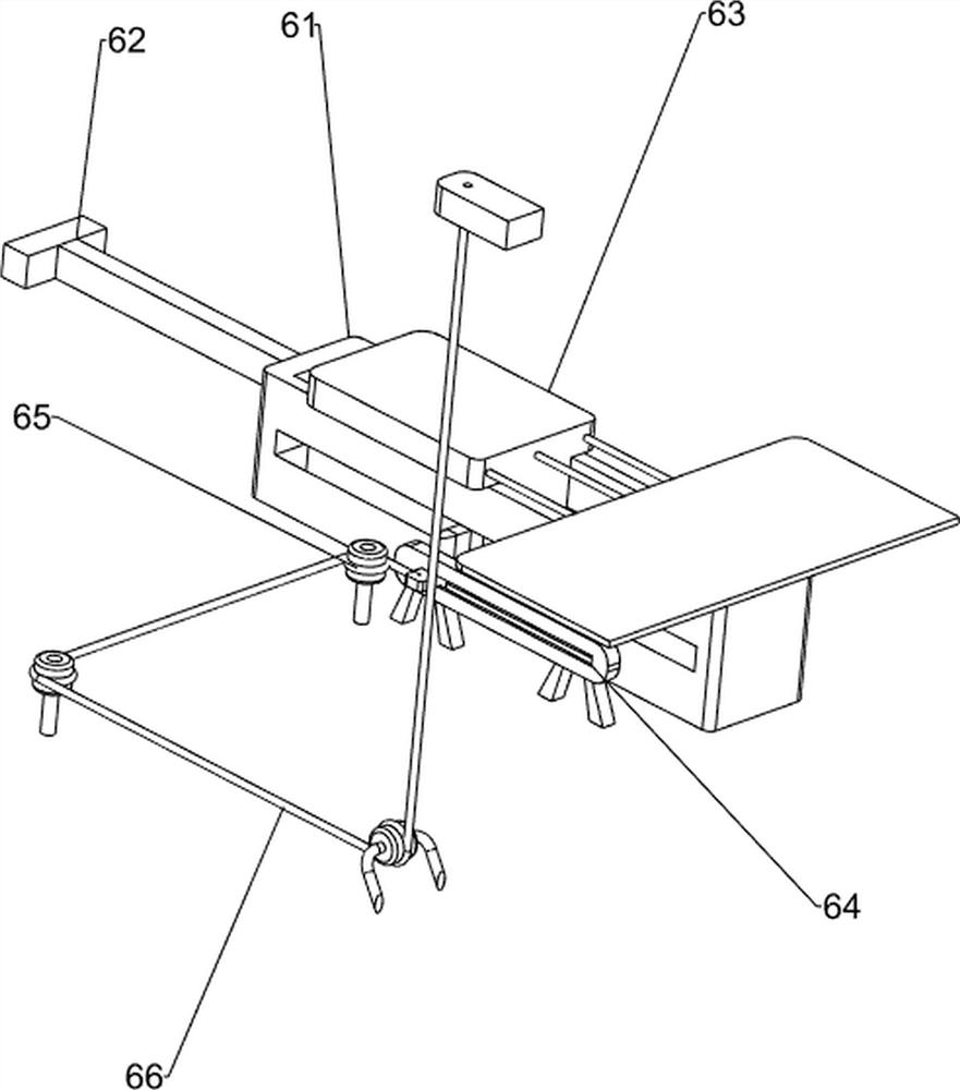
[0086] A utility knife automatically installs a blade device, such as figure 1 As shown, it includes worktable 1, air cylinder 2, unloading mechanism 3, charging mechanism 4 and suction mechanism 5. Cylinder 2 is installed on the left part of the front side of the top of the worktable 1; Feeding mechanism 3, a loading mechanism 4 is provided on the left side of the top rear of the worktable 1, and the charging mechanism 4 is connected with the unloading mechanism 3. A suction mechanism 5 is provided in the middle of the left side of the top of the worktable 1, and the middle of the right side of the top of the worktable 1 is provided. A pushing mechanism 6 is provided, and the pushing mechanism 6 is connected with the unloading mechanism 3 .

[0087] When people need to install the blade on the utility knife, this automatic blade installation device can be used. First, put the knife cover, the rear end cover and the blade into the unloading mechanism 3, the loading mechanism 4...

Embodiment 2

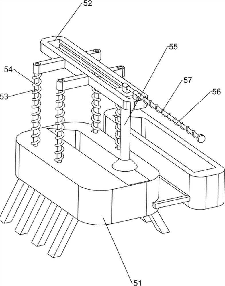
[0089] On the basis of Example 1, as Figure 2-10 As shown, the blanking mechanism 3 includes a first bracket 31, a base 32, a first spring rod 33, a first compression spring 34, a blanking frame 35, a fixing bolt 36, a first wedge block 37, a splint 38, a first wedge The rod 39 , the second compression spring 310 , the second wedge rod 311 and the third compression spring 312 , the first bracket 31 is symmetrically provided on the left and right sides of the top rear side of the workbench 1 , and the base 32 is provided on the left side of the top rear side of the workbench 1 . , the tops of the two first brackets 31 are provided with two first spring rods 33 , the four first spring rods 33 are all wound with a first compression spring 34 , and the bottom ends of the first compression springs 34 are connected with the first bracket 31 . A blanking frame 35 is slidably arranged between the four first spring rods 33, the top of each first spring rod 33 is provided with a fixing...

Embodiment 3

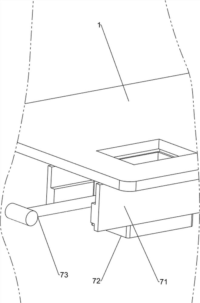
[0098] On the basis of Example 2, as Figure 11-13 As shown, it also includes a material storage mechanism 7, and the left part of the bottom rear side of the workbench 1 is provided with a material storage mechanism 7. The material storage mechanism 7 includes a fixed plate 71, a storage box 72 and a third push rod 73. The bottom of the workbench 1 is provided with a material storage mechanism 7. A fixed plate 71 is symmetrically arranged on the left part of the rear side, a storage box 72 is slidably arranged between the two fixed plates 71 , and a third push rod 73 is arranged on the rear wall of the storage box 72 .

[0099] The installed utility knives are pushed back into the storage box 72 by the sliding block 42, and people pull the third push rod 73 backward, so that the storage box 72 slides backward along the fixing plate 71, thereby taking out the collected utility knives, which is convenient for people Storage and Access.

[0100] It also includes an installation...


PUM


Abstract

The invention relates to an automatic blade installation device, in particular to a utility knife automatic blade installation device. The invention provides an automatic blade installation device for utility knives which simplifies installation steps, improves safety and improves installation efficiency. An automatic blade installation device for utility knives, comprising: a workbench, a cylinder is installed on the top of the workbench; a feeding mechanism, a feeding mechanism for placing a knife sleeve is provided on the top of the workbench; a loading mechanism, a charging mechanism is provided on the top of the workbench The feeding mechanism is connected with the unloading mechanism; the suction mechanism is provided with a suction mechanism on the top of the worktable; the pushing mechanism is provided with a pushing mechanism on the top of the worktable, and the pushing mechanism is connected with the unloading mechanism. In the present invention, the second wedge-shaped rod is moved down to contact and cooperate with the first wedge-shaped block, so that the second wedge-shaped rod slides to the outside, so as to achieve the effect of automatic cutting of the knife sleeve.

Description

technical field [0001] The invention relates to an automatic blade installation device, in particular to a utility knife automatic blade installation device. Background technique [0002] Utility knives, commonly known as carving knives or wallpaper knives, are knives for art and handicrafts. They are mainly used to cut things with softer textures. With a pull-out structure, this device only involves the installation of the knife sleeve, the blade and the rear end cover. The existing utility knife blade installation method mainly relies on manual manual insertion of the blades into the knife sleeve correspondingly one by one, and then the rear end cover is installed. This installation method has complicated steps, the blade is easy to cut the hand, and the efficiency is low. [0003] In order to make the utility knife blade installation more convenient, fast, safe and efficient, we designed an automatic utility knife blade installation device that can realize the automatic ...

Claims


Application Information

Patent Timeline
Patent Type & Authority Patents(China)
IPC IPC(8): B25B27/00
CPCB25B27/00
Inventor 欧阳年香
Owner 苏州上弓刀片有限公司
Why Eureka
Try Eureka