Fixing device for zipper machine

A technology of fixing device and zipper machine, which is applied in the direction of cloth feeding mechanism, sewing machine components, textiles and paper making, etc. It can solve problems such as difficult fixing, achieve the effect of reducing distance, preventing tilting and high safety

Inactive Publication Date: 2021-02-26
杭州永智信息科技有限公司
View PDF0 Cites 0 Cited by
  • Summary
  • Abstract
  • Description
  • Claims
  • Application Information

AI Technical Summary

Problems solved by technology

[0005] The purpose of the present invention is to provide a fixing device for zipper machines that can effectively fix textiles to solve the problem that most traditional zipper machines are difficult to fix during use

Method used


Image

  • Fixing device for zipper machine
  • Fixing device for zipper machine
  • Fixing device for zipper machine

Examples


Embodiment 1

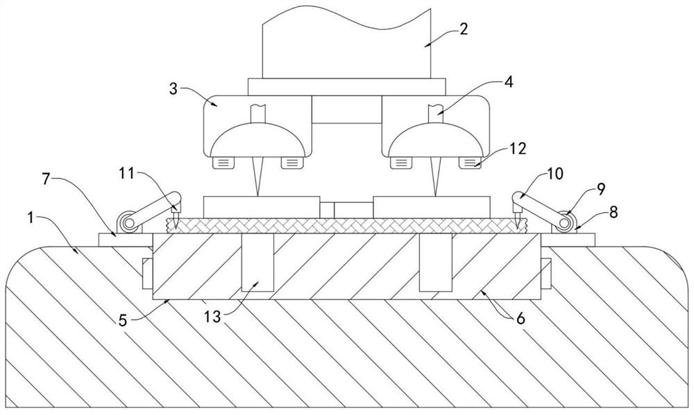
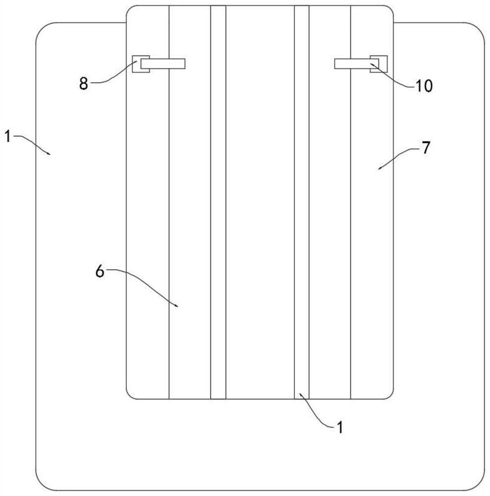
[0021] Such as Figure 1-2 As shown, a fixing device for a zipper machine includes a horizontally arranged placing table 1, the upper end of the placing table 1 is provided with a vertically arranged lifting rod 2, and the lower end of the lifting rod 2 is fixedly connected with two pressing heads 3, each pressing head 3 are provided with needles 4 throughout, and the lifting rod 2 will make the needles 4 reciprocate in the vertical direction under the drive of the driving device. The above is the prior art, and will not be repeated here.

[0022] It is worth mentioning that two symmetrically arranged rollers 12 are fixedly installed on the lower side wall of each pressing head 3, and the rollers 12 can effectively reduce the friction between the pressing head 3 and the textile, and prevent the pressing head 3 from making the placing table 1 The situation where the textile on the top is tilted occurs.

[0023] The upper side wall of the placing table 1 is provided with a vert...

Embodiment 2

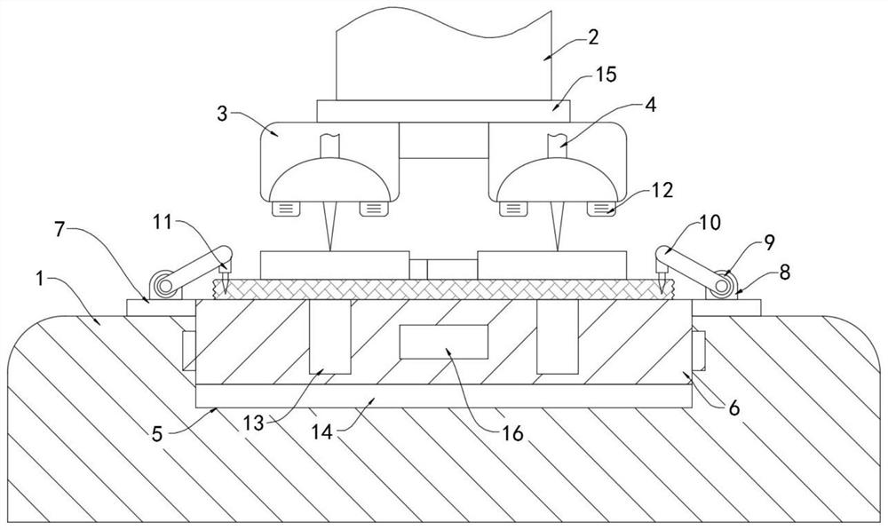
[0029] Such as image 3 As shown, the difference between this embodiment and Embodiment 1 is that: the lower side wall of the carrier plate 6 is fixedly connected with the lower electrode plate 14, and the pressing head 3 is fixedly connected with the upper electrode plate 15 arranged parallel to the lower electrode plate 14, The upper electrode plate 15 and the lower electrode plate 14 form a capacitor. It should be noted that an electromagnetic block 16 is fixedly embedded in the carrier plate 6 , and the electromagnetic block 16 is coupled to the capacitor formed by the upper electrode plate 15 and the lower electrode plate 14 .

[0030] In this embodiment, in the process of the lifting rod 2 moving up and down, the distance between the upper electrode plate 15 and the lower electrode plate 14 will change momentarily, and the change of the distance between the two electrode plates in the capacitor will cause charging and discharging. Therefore, at this time, the electromagn...


PUM


Abstract

The invention belongs to the field of zipper installation, and particularly relates to a fixing device for a zipper machine. The fixing device comprises a horizontally-arranged placing table, a vertically-arranged lifting rod is arranged at the upper end of the placing table, two pressing heads are fixedly connected to the lower end of the lifting rod, and a needle head is arranged on each pressing head in a penetrating mode. A vertically-arranged sliding groove is formed in the upper side wall of the placing table, a bearing plate is slidably connected into the sliding groove, the upper end of the bearing plate extends out of the sliding groove, connecting strips are fixedly connected to the side walls of the two sides of the bearing plate, a fixing pile is fixedly connected to the upperside wall of each connecting strip, and the two fixing piles are symmetrically arranged at the upper end of the bearing plate. By arranging fixing needles, after a textile fabric is placed on the bearing plate, connecting rods are pulled upwards and then loosened, the connecting rods can drive the fixing needles to be nailed on the textile fabric under the elastic action of coil springs, the textile fabric can be effectively fixed, the textile fabric is prevented from inclining in the zipper sewing process, and the sewing quality is guaranteed.

Description

technical field [0001] The invention belongs to the field of zipper installation, in particular to a fixing device for a zipper machine. Background technique [0002] Zippers are connected in a large number of fields such as clothing, bags, tents, etc., and a small part is also used for decoration, including cloth belts, tooth chains and tendon ropes. When fixing zippers to clothing, a zipper machine is often used. [0003] Most of the traditional zipper machines need to divide the textile to be connected into two parts in advance, and then connect the two cloth belts of the zipper to the corresponding textile. Make sure that the two parts of the fabric are aligned at all times, otherwise the zipper will easily tilt, which will eventually lead to unqualified stitching and affect the quality of the finished product. In addition, during the process of fixing by hand, the needles that are continuously stitched up and down are easily injured. To the hands of personnel, the secu...

Claims


Application Information

Patent Timeline
Patent Type & Authority Applications(China)
IPC IPC(8): D05B35/06
CPCD05B35/06
Inventor 朱桂军
Owner 杭州永智信息科技有限公司
Why Eureka
Try Eureka