
Efficient rainwater drainage system for sponge city

A technology of sponge city and drainage system, which is applied in the direction of waterway system, sewer system, and sewage discharge, etc. It can solve problems such as paralysis, blockage of sewage outlets, and traffic congestion, so as to avoid danger and reduce the possibility of road surface water. The effect of increasing emissions

Inactive Publication Date: 2021-02-26
王金培
View PDF6 Cites 3 Cited by
  • Summary
  • Abstract
  • Description
  • Claims
  • Application Information

AI Technical Summary

Problems solved by technology

[0003] At present, many water inlets are installed on the curbs of roads in cities. Since they are installed on the road surface, from the perspective of pedestrian safety, the water inlets are equipped with facilities such as manhole covers and safety nets, but manhole covers will affect the speed of rainwater flowing into underground pipes. When encountering heavy rain, especially in summer, it is easy to cause large areas of water accumulation, resulting in traffic congestion or even paralysis, and a large amount of garbage and silt will be brought in during the flushing process of rainwater, which can easily block the sewage outlet and cause more damage. Serious water accumulation, for this reason, we propose a sponge city efficient rainwater drainage system

Method used


Image

  • Efficient rainwater drainage system for sponge city
  • Efficient rainwater drainage system for sponge city
  • Efficient rainwater drainage system for sponge city

Examples


Embodiment

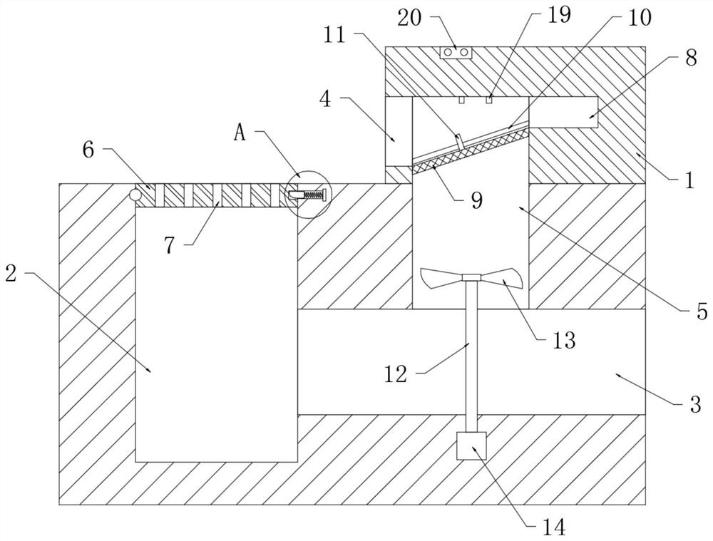
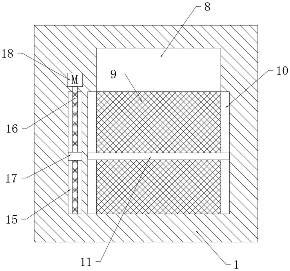
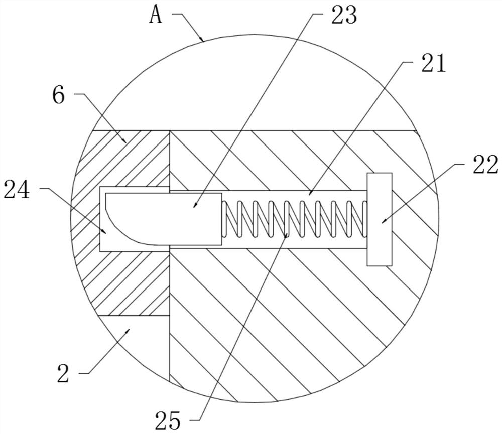
[0021] refer to Figure 1-3 , a high-efficiency rainwater drainage system for a sponge city, comprising a curb 1 and a drainage pipe 3 buried in the ground below the curb 1, and the road surface on one side of the curb 1 is provided with a silting tank 2 connected to the drainage pipe 3, and the silting A baffle 6 is rotatably connected to the notch of the groove 2, and the rotatable connection of the baffle 6 is provided with a torsion spring. The baffle 6 is provided with a plurality of through holes 7, and the side wall of the curb 1 is provided with a water inlet. 4. There is a drainage cavity 5 connected to the water inlet 4 in the curb 1, the lower end of the drainage cavity 5 is connected to the drain pipe 3, and a rotating shaft 12 is sealed and rotated on the inner wall of the drain pipe 3 directly below the drainage cavity 5 , the upper end of the rotating shaft 12 extends into the drainage cavity 5 and is fixedly connected with a spiral fan blade 13 , and the end of...


PUM


Abstract

The invention discloses an efficient rainwater drainage system for a sponge city. The efficient rainwater drainage system comprises a curb and a drainage pipe buried in the ground below the curb, a silt accumulation groove is formed in the road surface on one side of the curb and communicates with the drainage pipe, a baffle is rotationally connected to the groove opening of the silt accumulationgroove, a torsional spring is rotationally connected to the baffle, a plurality of through holes are formed in the baffle, a water inlet is formed in the side wall of the curb, and a drainage cavity is formed in the curb and communicated with the water inlet. The system has the advantages that when rainfall is large, accumulated water on the road surface rises to immerse two conductive blocks at the top of the drainage cavity, rainwater serves as a conductor to conduct a circuit where an electromagnet is located, a clamping block slides into a fixing groove to leave a clamping groove, the baffle is turned over and opened under the action of water pressure, the rainwater discharge amount is increased, and the possibility of accumulated water on the road surface is reduced; and meanwhile, awarning lamp can also be turned on to remind pedestrians not to approach, so that dangers are avoided.

Description

technical field [0001] The invention relates to the technical field of urban rainwater treatment devices, in particular to a high-efficiency rainwater drainage system for a sponge city. Background technique [0002] Sponge city is a new generation of urban stormwater management concept. It means that the city can be like a sponge, and has good elasticity in adapting to environmental changes and dealing with natural disasters caused by rainwater. It can also be called "water elastic city". The drainage system refers to the overall combination of drainage collection, transportation, water quality treatment and discharge facilities in a certain way. The general term for all levels of drainage ditches (pipes) and buildings used for waterlogging, waterlogging, and salt prevention. [0003] At present, many water inlets are installed on the curbs of roads in cities. Since they are installed on the road surface, from the perspective of pedestrian safety, the water inlets are equip...

Claims


Application Information

Patent Timeline
Patent Type & Authority Applications(China)
IPC IPC(8): E03F1/00E03F3/02E03F3/04E03F5/06B01D35/02B01D35/16F21S9/04F03B13/00F03B11/00
CPCB01D35/02B01D35/16E03F1/002E03F3/02E03F3/04E03F5/06F03B11/00F03B13/00F21S9/046Y02E10/20
Inventor 王金培
Owner 王金培
Learn More